


Content last revised on September 18, 2026
Field Diagnostics & Commissioning: Diode Peak Reverse Recovery Current and Switching in DD180N16S Topologies
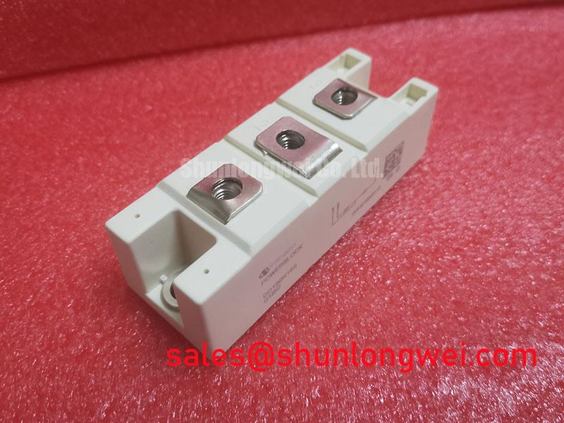
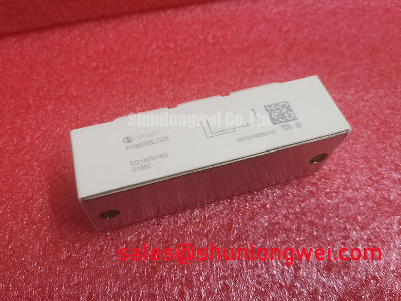
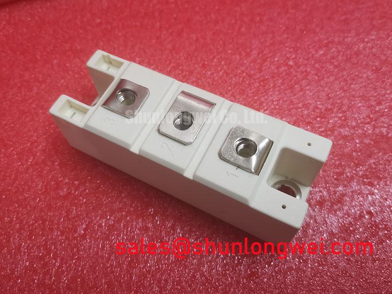
With the cabinet isolated and discharged, first verify that the installed module marking matches DD180N16S, then inspect its power terminals, baseplate contact area, and connected buswork for looseness, corrosion, heat discoloration, or contamination before applying any diagnostic stimulus. The Infineon DD180N16S is a PowerBlock diode module rated at 1600V and 180A. For maintenance teams handling medium frequency induction melting or hardening furnace power supplies, these specified ratings establish the device identity and the electrical limits that must be checked against the original equipment documentation.
| Parameter | Official Specification |
|---|---|
| Manufacturer | Infineon |
| Module type | PowerBlock diode module |
| Rated voltage | 1600V |
| Rated current | 180A |
Before commissioning a rectifier or commutation stage containing the DD180N16S, inspect the current path as a complete assembly rather than treating the diode module as an isolated item. Check that each conductor is seated flat against its intended terminal surface, that no cable lug can rotate under normal handling force, and that the DC link, snubber wiring, fuse holder, and associated switching devices are all returned to their documented locations. A diode module can pass a static resistance check while a poor terminal interface still creates localized heating during high current operation.
Reverse recovery behaviour is relevant where the DD180N16S commutates with an active switching branch. Peak reverse recovery current and recovery softness influence turn off stress, switching loss, and conducted or radiated noise within the surrounding converter. The injected official specifications identify the voltage and current ratings, but do not provide published values for reverse recovery peak current, recovery time, softness factor, or diode recovery waveform. Those values should therefore be taken only from the applicable original Infineon documentation or measured on the actual circuit with suitable high voltage differential and current probes.
During a controlled recommissioning test, compare switching waveforms with the known equipment topology and observe whether the reverse voltage transition is repeatable across operating conditions. Ringing, unexpected current overlap, or uneven sharing between parallel paths may indicate a layout, drive timing, snubber, or connection issue. They do not establish a single root cause on their own. Design Consideration: minimize the commutation loop area to reduce inductive overshoot, then verify peak voltage margins against the DC link and the 1600V module rating during switching tests.
Fuse selection also requires the original fuse coordination information. No fuse I²t coordination table is included in the available DD180N16S official parameter set, so a replacement fuse must not be selected from current rating alone. Verify the existing fuse class, semiconductor protection characteristics, fault clearing capability, and the equipment maker’s coordination documentation before energizing the repaired unit. In equipment with related high current stages, the TT570N16 can be reviewed as a separate peripheral topology component, subject to full electrical and mechanical verification by the system engineer.
Transient Dynamics & Electrical Design: Mechanical Mounting Torque Sequence and Thermal Parameters on DD180N16S
Remove accumulated dust from the heatsink channels and fan path before evaluating temperature related symptoms. Restricted airflow can raise the temperature of the module baseplate and nearby bus connections, making it difficult to distinguish a cooling issue from an electrical imbalance. With the module removed, inspect the heatsink for burrs, trapped debris, corrosion, or uneven contact marks. The mating faces should be clean and flat enough to support uniform thermal interface coverage.
The junction to case thermal resistance, often expressed as Rth(j c), is necessary for a calculated thermal model, yet no Rth(j c) value is included in the provided official data for this product. It must not be assumed from another PowerBlock package. The system integrator should obtain the correct thermal curves and mounting information from the original module documentation before calculating junction temperature or setting a thermal trip threshold.
Apply thermal interface material according to the equipment service documentation, using a controlled, even process that avoids dry regions and excessive buildup. Clamp the module progressively in a balanced sequence so the baseplate settles without distortion. Terminal screws and mounting screws can require different torque values, and neither torque value nor screw size is part of the available official DD180N16S parameter set. Use only the torque instruction applicable to the documented module and heatsink assembly.
⚠️ Maintenance Note: After any power module service, monitor contact temperature rise and recheck airflow integrity during the first controlled production cycle.
Condensation control matters when a furnace cabinet moves between cold standby and a warmer operating environment. Inspect cabinet seals, heater circuits where fitted by the machine builder, drainage paths, and fan operation before returning the power section to service. This is a Design Consideration for the enclosure and installation environment, not an individual DD180N16S qualification claim.
DD180N16S Thermal Electrical Optimization: RC Snubber Network Optimization for Practical Tuning
An RC snubber should be evaluated as part of the complete commutation path, including busbar geometry, transformer leakage behaviour, switching device timing, and the diode module position. The DD180N16S has an Official Datasheet voltage rating of 1600V, but the available data does not specify an RC network, a series saturable reactor, allowable circuit inductance, or a universal switching frequency range. Those values are system determined and should not be copied from an unrelated induction power supply.
When investigating repetitive voltage ringing, capture the waveform at the relevant power terminals using a measurement arrangement appropriate for the circuit voltage and transient environment. Compare tests with the original snubber fitted, after confirming its resistor condition, capacitor health, mechanical connections, and isolation from adjacent conductive debris. A degraded snubber can alter peak voltage and oscillation, but similar waveforms may also result from busbar changes, loose terminals, timing changes, or a failed peripheral component.
Engineering Recommendation: reduce parasitic loop inductance where practical to suppress turn off overshoot, while allowing the final RC and reactor values to be established by switching tests and component temperature observations. In resonant household appliance circuits, topology selection also changes device stress and commutation behaviour. For broader context, consult Resonant Topologies in Home Appliances; its principles should be translated to the actual equipment circuit rather than used as a replacement for the furnace manufacturer’s design records.
Where a repair requires assessment of a related module, DDB6U180N16RRP_B37 is a separately listed component for neutral comparison. Matching current and voltage labels alone does not establish interchangeability. Engineers should verify circuit function, terminal arrangement, thermal interface, isolation requirements, and original equipment documentation before considering any replacement.
Preventing Spurious Faults: Evaluating Post-Surge Reverse-Voltage Blocking Guidelines for DD180N16S
After a surge event, do not reapply power solely because the module shows no obvious external damage. Inspect the complete protection chain, including semiconductor fuses, surge suppression components where present, DC link connections, control supply stability, and the load side for a continuing fault. Verify terminal tightness and inspect the baseplate area for signs of uneven thermal contact before a controlled reapplication of power.
The sinusoidal 10 ms half cycle surge current rating, commonly identified as ITSM, is not included in the available official DD180N16S specification set. It must therefore be verified from the applicable manufacturer documentation before any post surge stress assessment. The same restriction applies to permissible junction temperature recovery windows, transient thermal impedance data, and reverse voltage reapplication criteria. No specific surge withstand level or recovery interval should be inferred from the 1600V, 180A ratings alone.
Use staged recommissioning that follows the machine builder’s safety procedure: verify insulation condition at the equipment level, confirm that auxiliary cooling is active, check control interlocks, and observe electrical and thermal behaviour under controlled load. If reverse blocking performance or commutation behaviour remains uncertain, remove the module from service for documented evaluation rather than repeatedly cycling the cabinet into fault.
For context on integrated power solutions and protection functions, Infineon Intelligent Power Modules provides manufacturer level information on IPM technology. The DD180N16S remains a diode module and should not be assumed to include IPM level sensing, gate drive, or protection functions. For applications requiring automotive qualification, review Infineon Automotive Qualified Power Modules against the specific documented qualification requirements; no automotive qualification claim is made here for the DD180N16S.