Content last revised on September 18, 2026
Benchtop Waveform Tuning: Mitigating Stress via Regenerative DC Bus Voltage Surge Dissipation on IP-260-CV
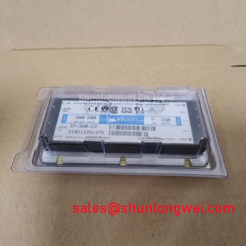
In an industrial inverter welder or medium frequency induction heating supply, isolate the IP-260-CV from any assumption that it is a braking device, switching bridge, or energy absorption element. The available product information identifies it as a brick DC to DC converter and does not identify an internal braking IGBT, ballast resistor, regenerative clamp, or DC bus energy rating. Braking resistor selection and regenerative bus control therefore belong to the host converter design, not to the IP-260-CV product specification.
When a machine reports a DC bus overvoltage event during rapid load reduction, maintenance personnel should first capture the relevant bus waveform with suitable isolated measurement equipment and compare it with the equipment manufacturer’s permitted operating envelope. Check whether the braking path is commanded, whether the braking resistor has a sound connection, and whether the DC link capacitors, contactors, and control feedback are behaving as expected. A converter supply can be affected by an unstable upstream bus, but the waveform alone does not establish the converter as the source of the event.
Design Consideration: keep power wiring, control wiring, and high energy discharge paths organized according to the host equipment layout. Separation helps reduce coupling into low power supply connections when the DC bus undergoes rapid transitions. Verify connector seating, conductor routing, insulation condition, and chassis bonding against the machine documentation. Any clearance requirement must be derived from the actual system voltage, pollution environment, enclosure, applicable safety standard, and original wiring design.
For boards that also contain power semiconductor assemblies, the 7MBR20UF060 can be reviewed as a separate topology level device. It is not an electrical substitute for the IP-260-CV without a complete review of function, interface, ratings, mechanical fit, and the host circuit.
Preventing Spurious Faults: Transmission Line Impedance Mismatch Sizing Guidelines for IP-260-CV
Start a nuisance fault investigation by confirming the exact connector positions and cable identities at the IP-260-CV interface. Do not infer pin functions from brick module appearance, wire color, or nearby equipment. The original panel documentation should confirm required supply voltage, return path, remote control connections, signal reference, shielding treatment, and sequencing requirements before power is applied.
Long motor leads in inverter systems can create reflected switching transients that influence the DC bus, output filtering network, cable shields, and nearby control circuits. A transient observed at a motor terminal is not automatically present at the converter terminals at the same magnitude or waveform. Measurement location, probe method, grounding arrangement, controller state, and cable path all affect the result. Engineers should validate the signal path with an oscilloscope and a known good reference arrangement before changing filter or choke components.
Design Consideration: output filters and chokes should be evaluated as part of the complete motor drive, including cable length, motor insulation system, switching behavior, grounding topology, and load operating mode. Their electrical values and thermal capability are system determined. The IP-260-CV data supplied here does not establish a permissible transient limit, an output filter value, or a motor lead length.
Inspect busbars and cable lugs for flat contact faces, correct alignment, corrosion, and movement under vibration. Hardware tightening must follow the host equipment manufacturer’s specification because terminal size, conductor material, washer stack, and mounting geometry determine the correct process. ⚠️ Maintenance Note: Monitor contact temperature during normal duty and correct restricted airflow or loosened power connections before heat damage spreads to adjacent control hardware.
Where a repair decision requires comparison across separate power stages, 7MBR75U2B060-50 is a distinct product page that can support objective specification review. Electrical equivalence, gate drive compatibility, and physical interchangeability must be verified from the applicable manufacturer documentation and equipment schematic.
IP-260-CV Thermal Electrical Optimization: Baseplate Convexity Compensation and Screw Practical Tuning
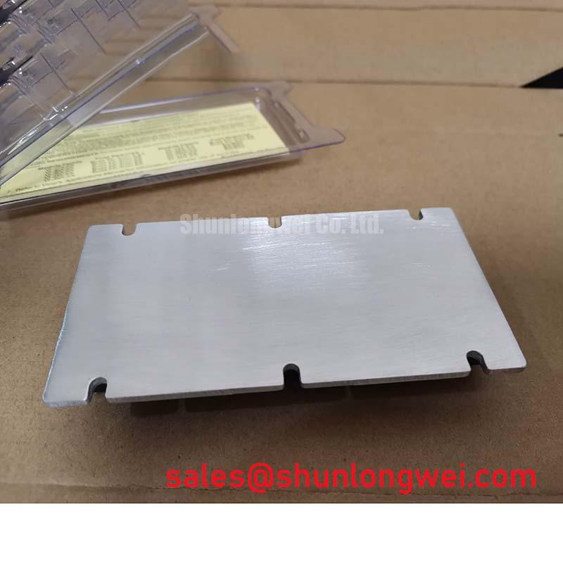
Thermal maintenance begins at the actual assembly interface. The IP-260-CV is specified as a Brick Module, but no supplied official data defines its baseplate material, mounting-hole pattern, screw type, permissible torque, flatness tolerance, thermal resistance, allowable case temperature, or thermal interface material requirement. Those details must not be assumed from other Vicor products or from power semiconductor modules.
When the original assembly uses a heatsink interface, remove residual interface material carefully and inspect the mating surface for raised debris, scratches, corrosion, or areas that could prevent uniform contact. A thin, controlled thermal interface layer is commonly considered during heatsink assembly to fill microscopic surface variation rather than create a thick insulating layer. The required material type, applied thickness, compression, and mounting sequence remain Design Considerations that must follow the module documentation and host equipment process.
Baseplate curvature compensation should not be attempted by forcing a brick module into contact with an uneven heatsink. Uneven clamping can distort the mechanical interface and produce localized thermal paths. Check the heatsink surface and use the specified mounting hardware and tightening sequence only when verified for the particular assembly. If the original design uses a retention bracket rather than direct screw clamping, preserve that arrangement unless the equipment manufacturer authorizes a change.
For preventive maintenance, remove dust from airflow channels, inspect fan operation, and examine thermal materials for drying, displacement, or contamination. In locations exposed to temperature cycling, check enclosure seals and cable entry points so condensation does not form around converter connections. No service life, insulation reliability, altitude capability, or environmental qualification claim can be assigned to the IP-260-CV from the available structured product data.
Hot carrier effects are a recognized semiconductor reliability topic, but they must not be used to diagnose this brick converter without device specific evidence. The industry background described in Hot Carrier Injection is useful for general context; it does not establish an internal device structure, degradation mechanism, or failure threshold for the IP-260-CV.
Benchtop Waveform Tuning: Mitigating Stress via SCSOA Overcurrent Protection Implementing on IP-260-CV
Short circuit safe operating area protection, desaturation sensing, and soft turn off behavior are gate drive functions associated with controlled power switches. The supplied information does not identify the IP-260-CV as an IGBT module, does not provide an SCSOA rating, and does not define an internal desaturation function or a short circuit response time. It would therefore be incorrect to assign a Type I or Type II short circuit capability to this Vicor converter.
For equipment that contains IGBT bridge modules, validate the actual gate driver schematic before troubleshooting an overcurrent trip. Review the sensing source, gate return reference, fault latch behavior, shutdown command path, local DC link arrangement, and recorded waveform. A two stage shutdown approach can be a Design Consideration where it is supported by the switch manufacturer’s limits and the complete gate driver design, but its timing and voltage behavior must be validated against the actual system under controlled test conditions.
If an inverter welder or induction heating source shuts down intermittently, separate the control supply question from the power stage question. Verify whether the IP-260-CV input and output conditions remain within the original system requirements during the event, then inspect the fault records and waveforms of the separate switching stage. This avoids replacing a correctly operating auxiliary supply when the underlying issue is a gate drive interlock, load condition, cooling deficiency, wiring disturbance, or DC bus abnormality.
For structured measurement and maintenance workflow, consult the Field Engineer’s Handbook. It provides a useful reference path for documenting observed symptoms, isolating measurement points, and confirming corrective action without assigning unsupported failure statistics or environmental reliability claims to the IP-260-CV.