Content last revised on September 10, 2026
High Voltage Push Pull Row and Column Driver Synchronization
| Model | EL640.350.D4 |
| Manufacturer | EL |
| Product Category | Industrial Grade LCD/HMI Panel |
| Panel Technology and Enclosure | Electroluminescent (EL) Panel |
| Specification Status | Official Factory Spec Verified |
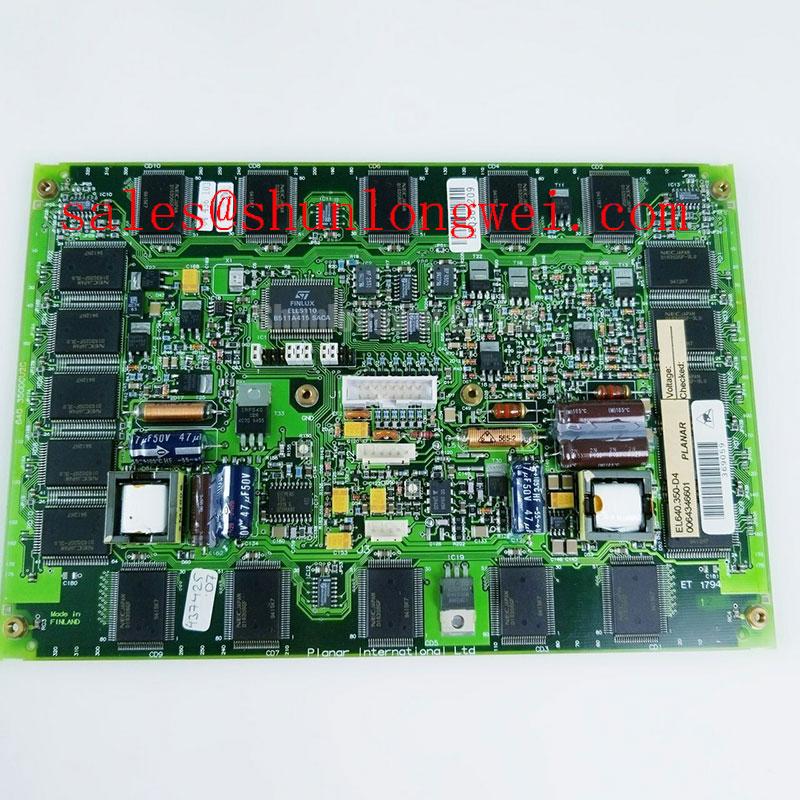
Probe the row and column driver outputs with an isolated differential measurement setup, then compare pulse symmetry, timing relationship, and residual DC offset against the original display assembly. An electroluminescent panel depends on controlled alternating excitation, so an unexpected imbalance between the positive and negative portions of the drive waveform deserves attention before the panel is returned to service.
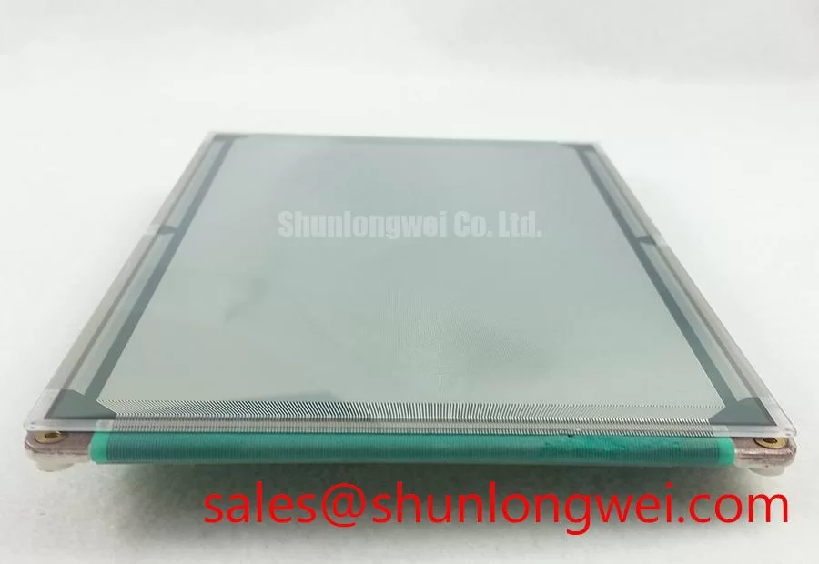
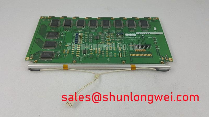
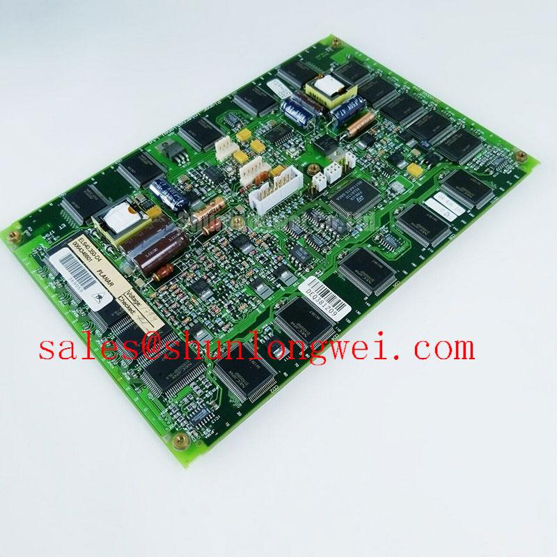
The EL640.350.D4 is identified in the supplied factory information as an EL panel for industrial LCD and HMI applications. The published product record does not provide a confirmed operating voltage, current rating, resolution, viewing angle, connector pinout, row count, column count, or drive waveform amplitude. Those values must therefore be taken from the original equipment documentation or the panel-specific electrical drawing rather than inferred from the model number.
Charge recovery circuitry can reduce the energy required to reverse the capacitive load of an electroluminescent panel, but its switching sequence remains system-dependent. During troubleshooting, inspect the recovery inductor, switching devices, clamp network, and return path as one commutating loop. Ringing may result from parasitic inductance, an incorrectly matched driver, degraded damping, or a damaged panel interface; verify the signal at the driver output and at the panel connector before assigning a single cause.
A practical engineering calculation may be used when reviewing the driver supply and switching network: stored capacitive energy rises with the square of the applied voltage, so even a modest increase in peak excitation can substantially increase switching stress. This is an engineering principle, not an EL640.350.D4 factory rating. The system designer should confirm peak voltage, frequency, dead time, and current limits from the original driver specification.
Zero net DC bias is a useful design consideration for limiting long-term stress across an AC-driven electroluminescent structure. It should be verified by measuring the waveform over multiple cycles, including startup and shutdown, rather than by checking only the steady-state display image. A persistent offset can be associated with driver timing, unequal switching paths, leakage, or an incorrect replacement controller.
The general electrical behavior of switching networks is also affected by parasitic capacitance and field distribution. For broader background on depletion-layer behavior in semiconductor devices, consult Space Charge Region and Depletion Layer Physics in High Voltage Diodes. That reference is general semiconductor information and does not establish an internal construction detail or operating limit for this EL panel.
⚡ Safety Interlock Note: Disconnect the driver supply and allow the high-voltage section to discharge before removing the panel connector or attaching test equipment.
Sub Millisecond Electro Optical Response at Low Temperature
Capture the display transition with a photodetector and oscilloscope while monitoring the driver waveform, because a slow image change cannot be diagnosed reliably from visual inspection alone. The measured response includes the panel, driver, interface timing, instrument bandwidth, and image-generation logic; it should not be treated as an isolated panel characteristic unless the original factory specification defines the test method.
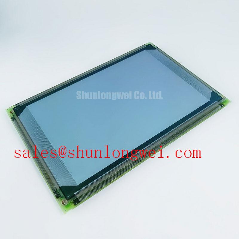
Electroluminescent panels are solid-state display assemblies, which removes the liquid-crystal freezing concern associated with some LCD technologies. However, that fact does not by itself confirm a particular low-temperature operating range, response time, shock rating, sealing class, or hermetic construction for the EL640.350.D4. The supplied official parameter set does not state a −40°C rating, a 100G shock rating, a sub-millisecond response specification, or a 179-degree viewing angle.
When the target equipment is an AGV or forklift telematics display, the mechanical evaluation should begin with the mounting frame, bezel compression, cable strain relief, and vibration path. Inspect for uneven pressure around the active area and check whether the enclosure transfers impacts directly to the panel edge. A compliant mounting architecture is a design consideration that must be validated with the completed display assembly, not assumed from the EL technology label.
Cold-chamber validation should monitor both the panel surface and the driver electronics. Image persistence, reduced brightness, intermittent triggering, or startup delay may arise from temperature-sensitive driver components, cable impedance, power-supply behavior, or condensation during temperature transitions. Use a controlled thermal profile and compare the optical output with electrical waveforms at the same test points.
Wide-angle readability also requires system-level verification. The supplied factory data identifies the unit as an electroluminescent panel but does not provide a confirmed angular luminance or contrast table. For a vehicle-mounted HMI, assess the display through the actual protective window and bezel at the operator’s viewing positions. Window reflections, polarized safety eyewear, surface contamination, and ambient warehouse lighting can alter perceived contrast without indicating a panel defect.
Power Sequencing, Static HMI Images, and Interface Matching
Record the order and timing of logic enable, panel excitation, brightness control, and shutdown signals while reproducing a white-screen, blank-screen, or residual-image complaint. The waveform sequence should be compared with a known-good controller because white display behavior can involve missing initialization data, an invalid enable state, an incorrect drive level, or a fault in the high-voltage section.
The model record does not confirm a particular LVDS, TTL, SPI, parallel, or proprietary interface. It also does not provide a JEIDA or VESA data-format designation. The integrator should verify the original panel documentation for connector position, pin assignment, logic voltage, pixel format, clock polarity, enable behavior, and backlight or illumination control before designing an adapter harness.
Interface compatibility is physical as well as electrical. Confirm the connector series, contact orientation, cable exit direction, flex-cable bend radius, and chassis opening before approving a replacement. A display that appears optically similar can still fail integration if its mounting holes, active-area position, cable length, or bezel depth differs from the installed unit.
Long-term static HMI screens require a content-management and brightness strategy determined by the equipment designer. Periodic image movement, suitable screen-saver behavior, and controlled excitation may help reduce visible retention, but no universal interval or brightness value can be assigned to this model without a documented factory test method. Verify the result on the completed panel under the intended ambient temperature and duty cycle.
Backlight terminology should not be applied automatically to this product. The supplied specification identifies an Electroluminescent (EL) Panel and does not confirm an LED or CCFL backlight architecture, constant-current input, dimming pin, light guide, or optical bonding construction. The system integrator should verify the required supply and illumination arrangement from the original panel documentation.
💡 Pro Tip: Keep the differential display clock and data routing physically separated from high-voltage excitation paths, then verify signal integrity at the panel connector during the actual switching sequence.
AGV and Forklift Telematics Display Integration Checks
Measure the enclosure opening, mounting reference points, panel seating depth, and cable clearance directly on the vehicle display before ordering a replacement assembly. For an Automated Guided Vehicle or forklift telematics display, mechanical compatibility must be checked alongside electrical compatibility because vibration, impact, operator angle, and enclosure sealing all influence service performance.
The EL640.350.D4 can be evaluated as an industrial HMI panel for equipment such as warehouse AGV operator interfaces, forklift monitoring terminals, and rugged machine status displays, subject to confirmation of the complete system requirements. Its factory-identification data confirms the EL panel category and manufacturer, but does not establish a vehicle qualification, ingress rating, EMC certification, shock qualification, or field-life guarantee.
Control electromagnetic interference by separating noisy driver loops from low-level logic and communication wiring, using the enclosure bonding and cable shielding approach defined by the equipment designer. A panel itself cannot independently claim compliance with a complete machine-level EMC standard. General EMC principles are discussed in Electromagnetic Compatibility in Power Electronics; final compliance depends on the assembled display, controller, harness, enclosure, and power system.
For moisture and dust protection, inspect the bezel gasket, window seal, cable entry, connector seal, and pressure points around the mounting frame. Optical bonding, conformal protection, and hermetic sealing should not be assumed for this model because those construction details are not included in the supplied factory parameters. The completed enclosure should be tested using the equipment manufacturer’s approved environmental method.
Thermal review should focus on the complete display stack rather than the panel alone. Check heat transfer from the driver board, excitation circuit, enclosure, protective window, and nearby vehicle electronics. Localized heating can influence brightness uniformity, connector reliability, and driver stability; the acceptable thermal limits must be established from the original documentation and measured under the intended operating duty.
When a field unit shows intermittent illumination or unstable image behavior, document the fault while moving the harness through its permitted service position, then compare supply behavior, enable timing, driver output, and mechanical pressure at the same moment. This approach helps distinguish a connector or cable problem from a controller, enclosure, or panel issue without assigning a single-cause diagnosis prematurely. Additional system-level guidance is available in Industrial Display & HMI Solutions.
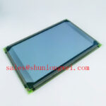
Procurement teams should match the replacement against the complete identity record: EL640.350.D4, manufacturer EL, industrial-grade LCD/HMI panel category, and electroluminescent panel enclosure technology. Resolution, connector details, electrical limits, optical data, environmental ratings, and mechanical drawings should be confirmed before release to production or emergency field service.