


Content last revised on June 23, 2026
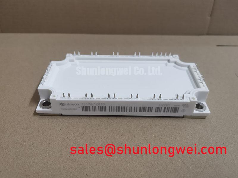
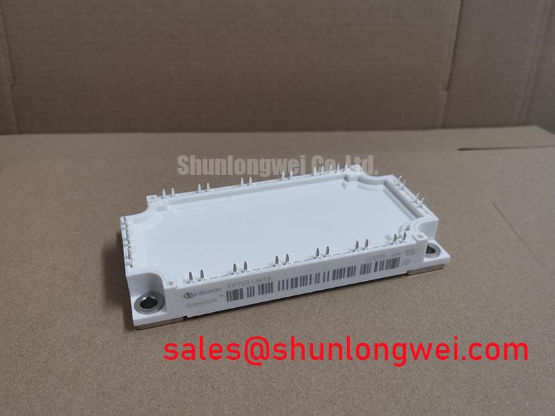
FP75R12KT3 | 1200V 75A IGBT Module | TRENCHSTOP™ IGBT3 for Efficient Power Conversion
An Engineering-Focused Overview of the FP75R12KT3 IGBT Module
Engineered for high-efficiency power conversion, the Infineon FP75R12KT3 is a six-pack IGBT module that balances performance and reliability. Its core value lies in the integration of TRENCHSTOP™ IGBT3 technology, offering a superior trade-off between conduction and switching losses. Key specifications include: 1200V | 75A | VCE(sat) 1.70V (typ.). This translates to two primary engineering benefits: reduced thermal load and enhanced system efficiency. This module directly addresses the challenge of achieving optimal performance in moderate frequency applications by minimizing total power losses. For motor drives operating under 20kHz, its balanced loss profile makes it a highly effective power stage solution.
Application Scenarios & Value
System-Level Benefits in Industrial Drives and UPS Systems
The FP75R12KT3 is optimally suited for applications where power efficiency and thermal stability are critical design drivers. Its primary deployments are in AC motor drives, uninterruptible power supplies (UPS), and solar inverters. What is the key advantage of its low VCE(sat)? It directly reduces conduction losses, which lowers the heat generated by the module and simplifies overall thermal management.
Consider a variable frequency drive (VFD) controlling a 15-22 kW industrial motor. The engineer's challenge is to maximize inverter efficiency to meet energy standards while minimizing the size and cost of the heatsink. The FP75R12KT3's typical VCE(sat) of 1.70V is crucial here. This low on-state voltage drop is like reducing friction in a mechanical system; less energy is wasted as heat for the same amount of current flow. This allows the VFD to run cooler, enabling a more compact and cost-effective heatsink design, or alternatively, providing greater thermal headroom for operation in high ambient temperatures. The integrated NTC thermistor further supports this by providing real-time temperature feedback for precise control and over-temperature protection, a vital feature for meeting safety standards like IEC 61800-5-1. While the FP75R12KT3 is ideal for this power range, for systems with lower current demands, the related FP50R12KT4 offers a 50A alternative within a similar package architecture.
Key Parameter Overview
Decoding the Datasheet for Optimal Efficiency and Thermal Design
The technical specifications of the FP75R12KT3 are a direct reflection of its intended use in high-performance power conversion systems. The parameters below have been grouped by function to facilitate engineering analysis.
| Inverter IGBT Characteristics (Tj=25°C) | |
|---|---|
| Collector-Emitter Voltage (V_CES) | 1200 V |
| Continuous Collector Current (I_C nom) | 75 A |
| Collector-Emitter Saturation Voltage (V_CE sat) @ 75A | 1.70 V (typ.) |
| Gate-Emitter Threshold Voltage (V_GE(th)) | 5.8 V |
| Inverter Diode Characteristics (Tj=25°C) | |
| Forward Voltage (V_F) @ 75A | 1.75 V (typ.) |
| Repetitive Peak Reverse Voltage (V_RRM) | 1200 V |
| Thermal and Mechanical Characteristics | |
| Thermal Resistance, Junction-to-Case (R_thJC) per IGBT | 0.27 K/W |
| Max. Junction Temperature (T_vj op) | 150°C |
| Housing | EconoPACK™ 2 |
Download the FP75R12KT3 datasheet for detailed specifications and performance curves.
Technical Deep Dive
A Closer Look at TRENCHSTOP™ IGBT3 for Balancing Conduction and Switching Performance
The core technology differentiating the FP75R12KT3 is Infineon's TRENCHSTOP™ IGBT3. This technology was specifically developed to find a 'sweet spot' for applications operating at switching frequencies typically between 4 kHz and 20 kHz. It masterfully balances two opposing characteristics: the on-state voltage drop (VCE(sat)) and the energy lost during switching (E_on, E_off). The trench-gate structure allows for a high density of charge carriers when the IGBT is on, significantly lowering the VCE(sat) and thus reducing conduction losses.
Simultaneously, the integrated field-stop layer addresses switching losses. You can think of this layer as a highly efficient braking system for charge carriers. During turn-off, it rapidly stops the flow of minority carriers that would otherwise create a lingering 'tail current', a major source of switching loss in older planar IGBTs. By minimizing this tail, the IGBT turns off faster and cleaner, reducing the energy dissipated as heat with every switching cycle. This balanced approach is why the FP75R12KT3 provides excellent total efficiency in a wide range of industrial applications without requiring designers to make extreme compromises between conduction and switching performance. For a deeper understanding of thermal metrics, see our guide on unlocking IGBT thermal performance.
Frequently Asked Questions
Engineering Questions on the FP75R12KT3
How does the TRENCHSTOP™ IGBT3 technology in the FP75R12KT3 benefit my design compared to older IGBT generations?
IGBT3 technology provides a much better balance between conduction losses (VCE(sat)) and switching losses. Unlike older technologies that forced a hard trade-off—where low VCE(sat) meant very high switching losses, or vice-versa—IGBT3 optimizes both. This results in higher overall inverter efficiency, especially in the 4-20 kHz switching frequency range common in motor drives and UPS systems.
What is the practical advantage of the integrated NTC thermistor for system reliability?
The integrated NTC thermistor provides a direct, real-time measurement of the module's substrate temperature. This allows the system's controller to implement precise over-temperature protection. It can trigger alarms, reduce output power (derating), or initiate a safe shutdown if the temperature exceeds safe limits, preventing catastrophic module failure and enhancing the long-term reliability and safety of the entire application.
How does the typical VCE(sat) of 1.70V influence heatsink selection for a motor drive application?
A lower VCE(sat) directly corresponds to lower heat generation (P_cond = VCE(sat) * I_C). With less heat to dissipate, you can often specify a smaller, lighter, and less expensive heatsink to maintain the same junction temperature. Alternatively, with an existing heatsink design, the lower thermal load provides a greater operating margin, improving system robustness in challenging thermal environments. Further explore this topic in our article about IGBT selection beyond VCE(sat).
For engineers and procurement managers evaluating power modules for their next design, the FP75R12KT3 presents a compelling, technically-sound solution. Its proven technology and industry-standard packaging provide a reliable foundation for developing efficient and robust power conversion systems. We encourage a detailed review of the official datasheet to validate its fit for your specific application requirements.