

Content last revised on June 23, 2026
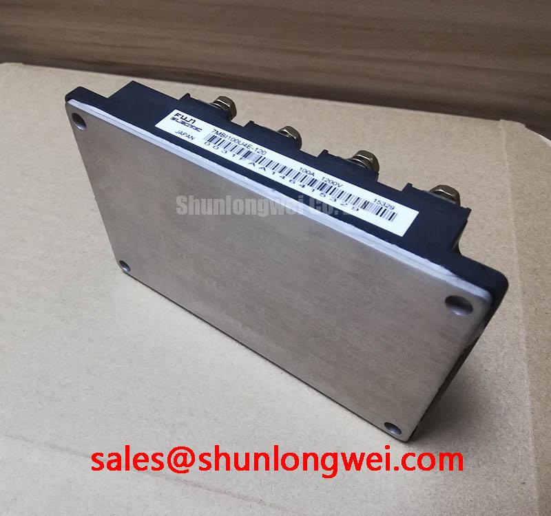
7MBI100U4E-120 | Fuji 1200V 100A 7-Pack IGBT Module
Engineering Insights into a High-Efficiency, Integrated Power Solution
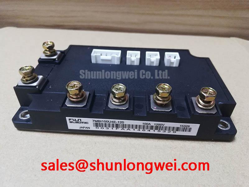
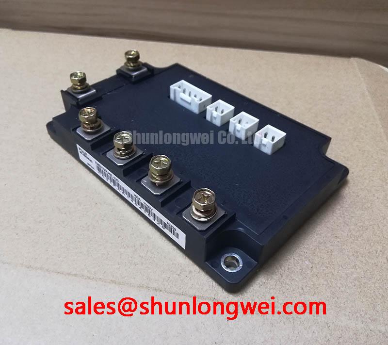
The 7MBI100U4E-120 is an advanced power module engineered to deliver superior efficiency and design simplification for motor drives by leveraging Fuji Electric's low-loss 7th generation U4-Series chip technology. This component integrates a full three-phase inverter and a brake chopper, making it an excellent solution for compact AC servo drives and general-purpose inverters that require robust regenerative braking control. Key performance metrics include: 1200V | 100A | Vce(sat) 1.70V (typ.). The primary engineering benefits are significantly reduced power loss and a simplified system layout, which accelerates development time. For designers of compact servo drives up to approximately 30kW, the 7MBI100U4E-120's integrated braking and low Vce(sat) offer an optimal balance of performance and physical footprint.
Application Scenarios & Value
System-Level Benefits in Compact Motor Control and Servo Applications
What is the primary benefit of its 7-in-1 design? A dramatically reduced component count and simplified power stage layout. The 7MBI100U4E-120 is specifically designed for applications where space, efficiency, and precise control are critical design constraints. Its performance characteristics make it a strong candidate for a range of demanding industrial systems.
- AC Servo Drives & Robotics: In multi-axis robotic arms or CNC machinery, achieving rapid acceleration and deceleration is key. The module's high-speed switching capability allows for higher Pulse Width Modulation (PWM) frequencies, enabling finer motor control and smoother motion profiles. The integrated brake chopper efficiently dissipates regenerative energy during deceleration, preventing DC bus overvoltage without requiring external braking circuits.
- General-Purpose Inverters: For equipment like pumps, fans, and conveyor systems, energy efficiency is a primary concern. The low collector-emitter saturation voltage (Vce(sat)) of the 7th generation U4-Series IGBTs minimizes conduction losses. This translates directly to lower operating temperatures, reduced heatsink requirements, and ultimately, a lower total cost of ownership.
- Elevators and Hoists: These applications involve frequent braking and energy regeneration. The integrated topology of the 7MBI100U4E-120 provides a compact and reliable solution for managing motor power and braking in a single package, simplifying the overall inverter design.
This module's 100A rating is well-suited for a significant range of mid-power applications. For systems requiring higher current handling for more powerful motors, the related 2MBI200NB-120 offers a dual-IGBT configuration with a 200A rating.
Key Parameter Overview
Decoding Key Specifications for High-Efficiency Inverter Design
The performance of the 7MBI100U4E-120 is defined by key electrical and thermal parameters rooted in its advanced chip technology and package design. The values below are critical for accurate system modeling, thermal management, and reliability assessment.
| Parameter | Symbol | Condition | Value |
|---|---|---|---|
| Collector-Emitter Voltage | Vces | Tj = 25°C | 1200 V |
| Continuous Collector Current | Ic | Tc = 80°C | 100 A |
| Collector-Emitter Saturation Voltage (Inverter) | Vce(sat) | Ic = 100A, Tj = 125°C | 1.70 V (typ.) / 2.10 V (max.) |
| Forward Voltage (FWD) | Vf | If = 100A, Tj = 125°C | 1.70 V (typ.) / 2.10 V (max.) |
| Maximum Junction Temperature | Tj max | - | 175 °C |
| NTC Thermistor Resistance | R25 | T = 25°C | 5 kΩ ± 1% |
Download the 7MBI100U4E-120 datasheet for detailed specifications and performance curves.
Frequently Asked Questions
Engineering Questions on Implementation and Performance
What is the primary advantage of the 7-in-1 configuration in the 7MBI100U4E-120?
The main advantage is system integration. By combining the three-phase inverter bridge and the brake chopper IGBT into a single, thermally optimized package, it reduces the PCB footprint, simplifies the bus bar design, lowers assembly complexity, and minimizes stray inductance between the stages. This leads to a more compact, reliable, and potentially more cost-effective overall system design.
How does the typical Vce(sat) of 1.70V impact thermal design for a servo drive?
A lower Vce(sat) directly reduces conduction power loss (P = Vce(sat) * Ic). Think of Vce(sat) as a "voltage toll" for current to pass through the switch; a lower toll means less energy is wasted as heat. This reduction in heat generation allows for the use of a smaller, lighter, and less expensive heatsink while maintaining a safe operating junction temperature, a critical factor in space-constrained servo drive enclosures.
What is the function of the integrated NTC thermistor and how should it be used?
The built-in NTC (Negative Temperature Coefficient) thermistor acts as an on-board temperature sensor. Its resistance decreases predictably as the module's temperature rises. By monitoring this resistance, the system's microcontroller can accurately gauge the IGBT's baseplate temperature in real-time. This data is crucial for implementing over-temperature protection (OTP), which can trigger alarms or shut down the drive to prevent catastrophic failure.
Is the brake chopper in the 7MBI100U4E-120 rated for the full 100A inverter current?
No, and this is a critical design consideration. The datasheet specifies the brake chopper section has a continuous collector current rating of 50A (at Tc=80°C). This is sufficient for managing regenerative energy in many motor applications but must be factored into the design of the external braking resistor and the expected braking duty cycle to ensure the chopper operates within its Safe Operating Area (SOA).
Technical Deep Dive
A Closer Look at the 7th Gen U4-Series Chip and Integrated Topology
What makes the 7MBI100U4E-120 efficient? Its performance stems from Fuji Electric's 7th generation U4-Series IGBT chip technology. This generation employs an advanced trench gate and thin wafer structure. This design optimizes the trade-off between conduction losses (Vce(sat)) and switching losses (Eon/Eoff), a fundamental challenge in power semiconductor design. The result is a device that operates with high efficiency across a broad range of operating frequencies, making it highly versatile.
The module's integrated topology provides benefits beyond simple component reduction. It's analogous to a system-on-chip (SoC) for power electronics. Rather than connecting discrete inverter and brake chopper modules with external bus bars, which introduce parasitic inductance, the 7-in-1 design features short, internal connections on a common substrate. This inherently lower inductance minimizes voltage overshoots during fast switching events, particularly during braking, which reduces stress on the components and can simplify the design of snubber circuits.
Strategic Outlook for System Design
Integrating a module like the 7MBI100U4E-120 represents a strategic decision to prioritize power density, higher efficiency, and faster time-to-market. The pre-packaged, pre-optimized 7-in-1 solution offloads significant power stage layout and thermal interface challenges from the design engineer. This allows development teams to focus resources on higher-level system aspects like control algorithms, user interface, and software, ultimately creating a more competitive end product. Adopting such integrated platforms is a key enabler for developing next-generation, compact industrial automation systems.