Content last revised on November 18, 2025
FP25R12W2T4: High-Efficiency 1200V, 25A PIM IGBT Module Engineered for Compact Drive Systems
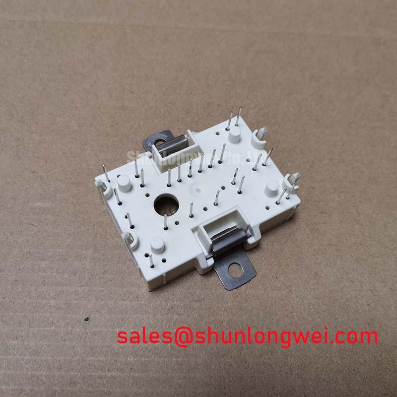
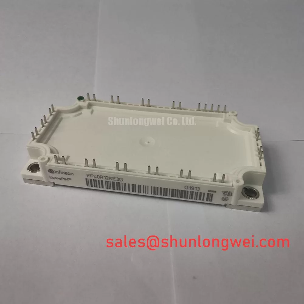
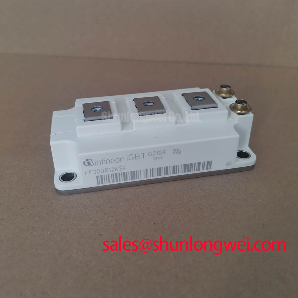
The FP25R12W2T4 from Infineon is a highly integrated Power Integrated Module (PIM) designed to optimize performance and power density in compact motor drives and inverter applications. This module leverages advanced TrenchSTOP™ IGBT4 technology to deliver a robust solution for power conversion systems requiring high efficiency and thermal stability. With core specifications of 1200V and 25A, it provides significant performance in a space-saving EasyPIM™ 2B housing. Key benefits include reduced switching losses and excellent thermal conductivity. This module directly addresses the engineering challenge of managing thermal loads in tightly packed enclosures without compromising on power output or reliability. For variable frequency drives where thermal performance dictates power density, the FP25R12W2T4's low thermal resistance makes it a superior choice.
Application Scenarios & Value
System-Level Benefits in Variable Frequency Drives and Servo Applications
The FP25R12W2T4 is engineered for demanding applications where efficiency and compact design are critical. Its primary value is demonstrated in systems like industrial Variable Frequency Drives (VFDs), servo drives, and auxiliary inverters for transportation and commercial vehicles. In these environments, engineers often face the challenge of dissipating heat effectively within restricted spaces. The module's low collector-emitter saturation voltage (VCE(sat)) of 1.85V (typical at nominal current) directly translates to lower conduction losses. This reduction in wasted heat simplifies the thermal management system, potentially allowing for smaller heatsinks and reducing overall system size and cost. What is the primary benefit of its integrated design? Simplified assembly and enhanced reliability by reducing stray inductance and component count.
For motor control systems, the integrated three-phase inverter, brake chopper, and NTC thermistor provide a complete power stage solution. This high level of integration minimizes external component count and simplifies PCB layout, accelerating the design cycle for systems such as commercial air conditioners, pumps, and fans. While the FP25R12W2T4 is ideal for 25A applications, for designs requiring higher current handling in a similar package, the FP50R12KT4 offers a 50A alternative.
Key Parameter Overview
Decoding the Specs for Efficient Power Conversion
The technical specifications of the FP25R12W2T4 are tailored for robust and efficient operation in high-frequency switching applications. The parameters below highlight its capability to manage both electrical and thermal stresses effectively, ensuring long-term reliability.
| Parameter | Value | Significance |
|---|---|---|
| Collector-Emitter Voltage (Vces) | 1200 V | Provides a substantial safety margin for applications running on 400V to 690V AC lines. |
| Continuous Collector Current (Ic) @ Tc=80°C | 25 A | Enables robust power delivery for low-to-mid-power motor drives and inverters. |
| Collector-Emitter Saturation Voltage (VCE(sat)) @ Ic=25A, Tvj=25°C | 1.85 V (Typ.) | Indicates low conduction losses, which minimizes heat generation and improves overall system efficiency. |
| Total Switching Losses (Ets) @ Ic=25A, VCE=600V | 2.90 mJ (Typ.) | Lower switching energy allows for higher frequency operation without excessive thermal stress, crucial for modern servo drive applications. |
| Thermal Resistance, Junction-to-Case (Rth(j-c)) per IGBT | 0.61 K/W (Max.) | Quantifies the module's excellent ability to transfer heat away from the semiconductor junction to the heatsink. |
| Short-Circuit Withstand Time (tsc) | 10 µs | Ensures the device can survive brief, catastrophic fault conditions, enhancing system ruggedness. |
Download the FP25R12W2T4 datasheet for detailed specifications and performance curves.
Technical Deep Dive
Inside the TrenchSTOP™ IGBT4 and Emitter Controlled Diode
The core of the FP25R12W2T4's performance lies in its use of Infineon's TrenchSTOP™ IGBT4 technology. Unlike older planar IGBT technologies, the TrenchSTOP™ design creates a vertical gate structure. This can be compared to building a multi-story car park instead of a sprawling single-level lot; it dramatically increases the density of charge carriers that can be controlled in the same silicon area. The engineering result is a sharp reduction in VCE(sat) and a significant decrease in switching losses, particularly at the higher frequencies common in modern AC motor drives. This efficiency allows designers to push for higher power density without risking thermal runaway.
Paired with the IGBT is an Emitter Controlled 4 (EC4) diode, which is co-packed and optimized for soft switching behavior. Think of the diode as a shock absorber for the electrical current during the IGBT's turn-off phase. A poorly matched diode can cause voltage overshoots and electromagnetic interference (EMI). The EC4 diode is specifically engineered to have a soft recovery characteristic, which minimizes these oscillations. This synergy between the IGBT and the freewheeling diode not only improves efficiency but also simplifies the design of snubber circuits and EMI filtering, leading to a more reliable and compliant end-product.
Frequently Asked Questions (FAQ)
How does the integrated NTC thermistor in the FP25R12W2T4 benefit the system design?
The integrated Negative Temperature Coefficient (NTC) thermistor provides a direct, real-time measurement of the module's baseplate temperature. This allows the system's controller to implement precise over-temperature protection or to dynamically adjust performance based on the thermal load. It eliminates the need for an external temperature sensor, reducing component count, simplifying assembly, and improving the accuracy of thermal monitoring.
What are the primary considerations when designing a gate drive circuit for this 1200V IGBT module?
For the FP25R12W2T4, a robust gate drive circuit is critical for achieving optimal switching performance and reliability. Key considerations include providing the recommended gate-emitter voltage (typically +15V for turn-on and -8V to -15V for turn-off) to ensure full enhancement and prevent parasitic turn-on. Additionally, keeping the gate drive loop traces as short and wide as possible is crucial to minimize stray inductance, which can cause voltage ringing and potentially damage the IGBT. What is the impact of a low Rth(j-c) value? A lower thermal resistance allows for more efficient heat transfer, enabling higher power output or the use of a smaller heatsink.
Engineering Support & Next Steps
To facilitate your design and evaluation process, our team of application engineers is available to provide technical support. We can assist with thermal simulations, gate drive design considerations, and component selection to help you fully leverage the capabilities of the FP25R12W2T4 module in your specific application. Contact us for detailed datasheets, application notes, and to discuss your project requirements.


