


Content last revised on May 27, 2026
Infineon FZ400R17KE3 IGBT Module: Engineering Analysis for High-Voltage Power Systems
A Definitive Review for OEM Engineers and Procurement Specialists
The Infineon FZ400R17KE3 is an industry-standard IGBT module engineered to deliver robust performance and high reliability in demanding high-voltage power conversion applications. With core specifications of 1700V | 400A | Tvj op = 150°C, this module provides a dependable foundation for systems requiring significant power handling. Key engineering benefits include exceptional operational robustness from its high breakdown voltage and optimized thermal performance. This module directly addresses the challenge of designing efficient and durable inverters for 690V AC line systems, offering a substantial safety margin. For high-power industrial drives operating on 690V AC grids, the FZ400R17KE3's thermal characteristics and voltage rating establish it as a premier choice for system reliability.
Key Parameter Overview
Decoding the Specs for Thermal Stability and Electrical Performance
The technical specifications of the FZ400R17KE3 are foundational to its performance in high-stress environments. The following parameters have been selected from the official datasheet to support system-level design and thermal management decisions.
| Inverter IGBT: Maximum Rated Values | |
| Collector-Emitter Voltage (VCES) | 1700 V |
| Continuous Collector Current (IC nom) | 400 A |
| Repetitive Peak Collector Current (ICRM) | 800 A |
| Gate-Emitter Voltage (VGES) | ±20 V |
| Inverter IGBT: Characteristic Values | |
| Collector-Emitter Saturation Voltage (VCE sat) at IC=400A, Tvj=25°C | 1.90 V (Typ.) / 2.35 V (Max.) |
| Gate Threshold Voltage (VGE(th)) | 5.8 V (Typ.) |
| Total Switching Energy (Eon + Eoff) at IC=400A, VCE=900V, Tvj=125°C | 290 mJ (Typ.) |
| Inverter Diode: Characteristic Values | |
| Forward Voltage (VF) at IF=400A, Tvj=25°C | 1.85 V (Typ.) / 2.25 V (Max.) |
| Reverse Recovery Energy (Erec) at IF=400A, VR=900V, Tvj=125°C | 120 mJ (Typ.) |
| Thermal and Mechanical Specifications | |
| Thermal Resistance, Junction to Case (RthJC) per IGBT | 0.075 K/W (Max.) |
| Thermal Resistance, Junction to Case (RthJC) per Diode | 0.12 K/W (Max.) |
| Operating Junction Temperature (Tvj op) | -40 to +150 °C |
| Isolation Voltage (Visol) | 4000 V (RMS, f=50 Hz, t=1 min.) |
Download the FZ400R17KE3 datasheet for detailed specifications and performance curves.
Application Scenarios & Value
System-Level Benefits in Industrial Drives and Renewable Energy
The FZ400R17KE3 is an optimal solution for power converters connected to three-phase 690V AC industrial grids, which can experience DC bus voltages approaching 1000V. What is the primary benefit of its high voltage rating? It provides a critical safety margin against transient overvoltages common in such environments, enhancing long-term system reliability. This makes it a workhorse component for applications such as large Variable Frequency Drives (VFDs), industrial motor controls, and the grid-side converters in wind turbines and large-scale solar inverters.
Consider the design of a VFD for a heavy-duty conveyor system. The engineer's primary challenge is managing heat dissipation under high, fluctuating loads to prevent overheating and ensure a long operational life. The FZ400R17KE3's maximum thermal resistance from junction to case (RthJC) of 0.075 K/W is a decisive parameter. This low thermal resistance acts like a wide pipeline for heat, allowing it to be efficiently transferred from the semiconductor chip to the heatsink. A lower RthJC value directly translates to a lower operating junction temperature for a given power loss, simplifying heatsink design, reducing overall system size, and improving the power cycling capability of the entire drive. This robust thermal design is a cornerstone of its value proposition. For systems requiring higher current output within the same voltage class, the FZ600R17KE3 offers a direct upgrade path.
Frequently Asked Questions (FAQ)
How does the 1700V rating of the FZ400R17KE3 benefit designs for 690V AC systems?
A standard 690V AC line can produce a rectified DC bus voltage of approximately 975V. The 1700V VCES rating provides a substantial safety margin of over 70%, protecting the module against voltage spikes caused by inductive loads or grid fluctuations. This robust derating is a key factor in building highly reliable systems with extended operational lifespans, a critical requirement in industrial automation and renewable energy infrastructure.
What is the engineering significance of the Trenchstop™ IGBT3 technology used in this module?
This module utilizes Infineon's well-established Trenchstop™ IGBT3 technology. What is the key advantage of this technology? It is engineered to provide a balanced performance between low collector-emitter saturation voltage (VCE(sat)) and reduced switching losses. This optimization results in lower overall power dissipation across a wide range of operating frequencies, directly contributing to higher inverter efficiency and reduced thermal management requirements for the design engineer.
Technical Deep Dive
A Closer Look at the EconoPACK™ 3 Housing and Thermal Interface
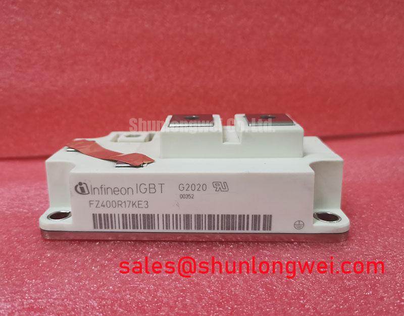
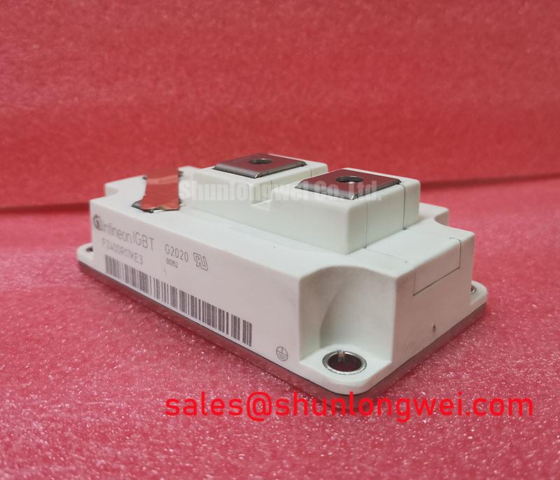
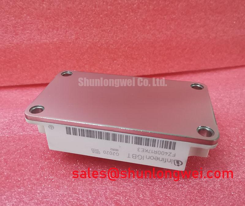
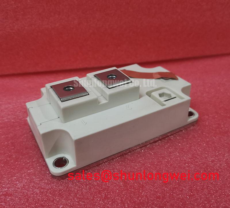
The performance of a high-power IGBT module is not solely determined by its silicon. The FZ400R17KE3 is housed in the industry-standard EconoPACK™ 3 package, a design that directly addresses practical engineering challenges in manufacturing and thermal management. The package features a flat baseplate, which is crucial for achieving a low-resistance thermal connection to the system's heatsink.
The quality of this connection is paramount. Even a small void or inconsistency in the Thermal Interface Material (TIM) between the module and the heatsink can create a thermal "hotspot," leading to premature failure. The EconoPACK™ 3's design facilitates a uniform and reliable application of TIM. This simplifies the assembly process and ensures that the low RthJC specified in the datasheet can be realized in the final application. For system designers, this means more predictable thermal performance and a reduced risk of field failures related to insufficient cooling, a critical aspect of managing the total cost of ownership for high-power electronic systems.
To further explore component options or discuss your specific design requirements, please review our portfolio of high-power IGBT modules. Our team can provide the technical data needed to support your evaluation and procurement process, ensuring you select a component that aligns with your system's performance and reliability targets.