


Content last revised on March 31, 2026
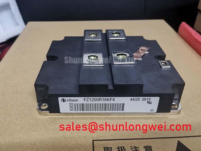
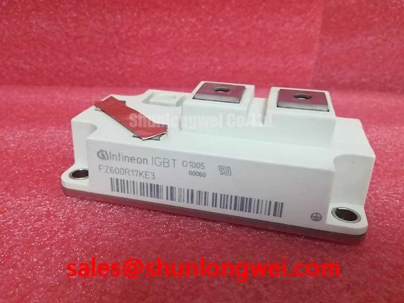
Infineon FZ600R17KE3 IGBT: 1700V/600A Module Analysis
Engineered with TrenchSTOP™ IGBT3 technology, the FZ600R17KE3 minimizes losses to maximize efficiency in high-power converters and drives.
The Infineon FZ600R17KE3 is a high-power single switch IGBT module designed for demanding industrial applications. It delivers a robust performance profile defined by key specifications: 1700V Collector-Emitter Voltage | 600A Nominal Collector Current | 2.0V typical VCE(sat). This module offers two primary engineering benefits: significantly reduced switching losses and superior thermal performance. For engineers evaluating power stages, a key question is how to balance conduction and switching performance; the FZ600R17KE3 addresses this by leveraging Infineon's TrenchSTOP™ IGBT3 technology to achieve a low VCE(sat) without compromising switching speed, enabling higher operational efficiency.
Intra-Series Comparison & Positioning
Comparative Placement: Finding the FZ600R17KE3's Niche
Within Infineon's extensive portfolio of 1700V IGBT modules, the FZ600R17KE3 is positioned as a highly efficient solution for applications where both conduction and switching losses are critical design considerations. Compared to modules designed for lower frequency operation, its TrenchSTOP™ IGBT3 and Emitter Controlled 3 diode technology provide a superior balance, leading to lower total power dissipation. For systems operating in the medium frequency range, such as industrial motor drives or large-scale Solar Inverter applications, this translates directly into smaller heatsink requirements and increased power density. In contrast to higher current modules like the FZ900R12KE4, the FZ600R17KE3 offers a more cost-effective solution for systems where 600A is sufficient, without over-specifying the power stage.
Key Parameter Overview
Core Electrical & Thermal Specifications
The performance of the FZ600R17KE3 is defined by its electrical and thermal characteristics, which are critical for system design and simulation. All parameters are based on the official manufacturer datasheet.
| Electrical Characteristics (IGBT) at Tvj = 25°C unless otherwise specified | |
|---|---|
| Collector-Emitter Voltage (V_CES) | 1700 V |
| Nominal Collector Current (I_C nom) at Tc=80°C | 600 A |
| Collector-Emitter Saturation Voltage (V_CEsat) at I_C=600A, V_GE=15V, Tvj=125°C | 2.40 V (typ.) |
| Gate-Emitter Threshold Voltage (V_GE(th)) | 5.8 V (typ.) |
| Total Switching Energy (E_ts) at I_C=600A, V_CE=900V, V_GE=±15V, Rg=2.7Ω, Tvj=125°C | 230 mJ (typ.) |
| Thermal & Mechanical Characteristics | |
| Thermal Resistance, Junction-to-Case (Rth(j-c)) per IGBT | 0.040 K/W (max.) |
| Maximum Junction Temperature (Tvj max) | 150 °C |
| Isolation Voltage (V_isol) | 4.0 kV (RMS, f=50 Hz, t=1 min) |
For detailed parameters and operational curves, please refer to the official FZ600R17KE3 datasheet.
Application Scenarios & Value
Maximizing System Efficiency: Key Application Areas
The FZ600R17KE3 is engineered to enhance performance in high-power conversion systems where efficiency and reliability are paramount. Its combination of high voltage rating and low losses makes it an excellent component for a range of applications:
- High-Power Converters: In large-scale industrial converters, the module's low VCE(sat) reduces conduction losses, which are a major contributor to heat generation. This directly improves the overall system efficiency.
- Motor Drives: For high-power Variable Frequency Drive (VFD) systems, the module's optimized switching characteristics enable higher PWM frequencies, leading to reduced motor noise, lower torque ripple, and improved control dynamics.
- Wind Turbines: The module's 1700V rating provides a significant design margin for grid-tied inverters in renewable energy systems, particularly in regions with fluctuating grid voltage. Its robust thermal performance ensures long-term reliability in harsh operating environments. For a deeper understanding of how these components are essential in renewables, explore our guide on the role of IGBTs in wind-to-grid conversion.
- Uninterruptible Power Supplies (UPS): In large commercial and industrial UPS systems, the efficiency gains provided by the FZ600R17KE3 reduce operating costs by minimizing wasted energy.
For high-power motor drives where minimizing thermal load is the primary goal, the FZ600R17KE3's low typical VCE(sat) of 2.40V at 125°C makes it a superior selection.
Industry Insights & Strategic Advantage
Strategic Implications of Lower Loss Operation
The drive for higher efficiency in power electronics is not just about reducing energy consumption; it's a strategic imperative. Regulations worldwide are tightening standards for energy efficiency in industrial equipment, and market demand for more compact, powerful, and cost-effective solutions is accelerating. What is the impact of low-loss components? Modules like the Infineon FZ600R17KE3 directly address these trends. Its lower switching and conduction losses mean less heat is generated for a given amount of power processed. This engineering advantage cascades through the entire system design: it allows for smaller, less expensive cooling systems, enables higher power density, and ultimately lowers the total cost of ownership (TCO) for the end equipment. In sectors like renewable energy, higher inverter efficiency means more marketable power is delivered to the grid, improving the financial viability of the entire project. For further reading, see how to go about decoding IGBT datasheets to make informed selections.
Frequently Asked Engineering Questions
Common Queries on the FZ600R17KE3 Module
1. How does the positive temperature coefficient of VCE(sat) in the FZ600R17KE3 benefit parallel operation?
The positive temperature coefficient of VCE(sat) is a critical feature for ensuring stable current sharing when paralleling multiple IGBT modules. As a module heats up under load, its on-state voltage (VCE(sat)) increases. This inherently counteracts the tendency for that specific module to draw more current, forcing the current to redistribute more evenly among the other parallel modules. This self-balancing mechanism prevents thermal runaway in a single device, greatly simplifying the design of high-current power stages and enhancing overall system reliability.
2. What are the key considerations for the gate drive design for this 600A/1700V module?
A robust gate drive design is crucial. Key considerations include: providing a stable gate voltage (typically +15V for turn-on and -15V for turn-off) to ensure full enhancement and prevent spurious turn-on. The gate driver must also be capable of sourcing and sinking sufficient peak current to charge and discharge the IGBT's input capacitance quickly, which is essential for achieving the low switching losses specified in the datasheet. Using a low-inductance layout and appropriate gate resistors (Rg) is also vital to manage switching speed and control voltage overshoots (dV/dt) and ringing.
Success Stories / Deployment Snippets
Deployment Profile: A Glimpse into Real-World Integration
While specific customer deployments are confidential, modules with the characteristics of the FZ600R17KE3 are commonly integrated by leading manufacturers of industrial automation and renewable energy systems. A typical use case involves a 250 kW to 400 kW three-phase inverter for a commercial-scale wind turbine. In this scenario, engineers selected this module to upgrade a previous-generation design. The primary objective was to increase the inverter's power output without increasing the physical footprint of the power cabinet. The lower total losses of the FZ600R17KE3 allowed them to achieve the power increase while staying within the thermal dissipation limits of the existing enclosure and heatsink assembly, avoiding a costly mechanical redesign and accelerating time-to-market.
Technical Deep Dive
Anatomy of Efficiency: TrenchSTOP™ IGBT3 Performance
The core of the FZ600R17KE3's performance lies in the Infineon TrenchSTOP™ IGBT3 (T3) technology. This technology represents a significant evolution in IGBT design, creating a device with a much thinner N-drift region compared to older Non-Punch-Through (NPT) designs. This is achieved by incorporating a "field stop" layer. The engineering result is a dramatic reduction in the collector-emitter saturation voltage (VCE(sat)). What is the benefit of a lower VCE(sat)? It acts like a smaller tollbooth for current; the lower the voltage drop when the switch is on, the less power is wasted as heat. The FZ600R17KE3 specifies a typical VCE(sat) of just 2.40V at its nominal current and operating temperature of 125°C. This directly translates to lower conduction losses—a critical factor in applications with high duty cycles, such as motor drives. Simultaneously, the T3 technology maintains excellent control over switching losses (Eon and Eoff), providing a well-balanced profile for systems that require both efficient conduction and fast switching.
This module is an excellent candidate for designers looking to push the boundaries of power density and efficiency in high-voltage industrial applications. For technical consultation or to discuss your specific design needs, please reach out to our engineering support team.