


Content last revised on March 28, 2026
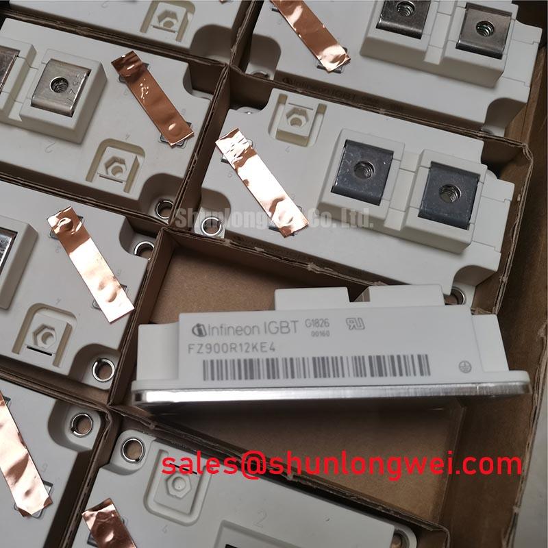
Infineon FZ900R12KE4 IGBT: Low Loss 1200V 900A Module
Engineered for high-efficiency power conversion, the Infineon FZ900R12KE4 leverages TRENCHSTOP™ IGBT3 technology to deliver exceptional performance in high-power applications. This module provides a robust foundation for designs where minimizing total power loss is a primary objective. The low saturation voltage directly reduces conduction losses, which is critical for improving the thermal performance and overall energy efficiency of an inverter.
Top Specs: 1200V | 900A | VCE(sat) 1.70V (typ)
Key Benefits:
- Reduced overall power losses.
- Enhanced system efficiency.
Deconstructing TRENCHSTOP™ IGBT3: The Core of FZ900R12KE4's Efficiency
The performance of the FZ900R12KE4 IGBT module is fundamentally rooted in its use of Infineon's TRENCHSTOP™ IGBT3 technology. This established chip generation represents a significant optimization between conduction and switching losses. Unlike earlier planar gate technologies, the trench gate structure allows for a higher channel density, which directly contributes to a lower collector-emitter saturation voltage (VCE(sat)). What is the primary benefit of its low VCE(sat)? Significantly lower conduction losses, which translates to less waste heat and higher system efficiency.
Furthermore, the IGBT3 technology provides a soft switching behavior, which is beneficial for managing electromagnetic interference (EMI) within the system. The module also incorporates an Emitter Controlled 3 diode, which is co-packed and optimized for low forward voltage and soft recovery characteristics. This synergy between the IGBT and the freewheeling diode is essential for minimizing turn-on losses and reducing voltage overshoots during switching transitions, further enhancing the module's overall efficiency and reliability. For engineers working on high-power systems, a comprehensive grasp of these characteristics is vital, as detailed in guides on decoding IGBT datasheets.
Meeting Energy Mandates: The FZ900R12KE4's Role in Modern Power Systems
In today's industrial landscape, escalating energy costs and stringent efficiency regulations are driving the demand for advanced power conversion technologies. The FZ900R12KE4 directly addresses this trend by enabling the design of systems that waste less energy. The module's low total power losses—a combination of its low VCE(sat) and optimized switching characteristics—allow designers to meet or exceed efficiency standards like IE3/IE4 for motors. This efficiency not only reduces the operational carbon footprint but also lowers the total cost of ownership (TCO) for the end-user through direct energy savings. The robust thermal performance allows for more compact heatsink designs, contributing to smaller and more power-dense inverter solutions.
Datasheet-Driven Comparison: FZ900R12KE4 Parameter Cross-Reference
To support your component evaluation process, the following table presents key performance indicators for the FZ900R12KE4. This data is provided to facilitate a direct, fact-based comparison against other potential solutions for your design. For applications requiring different current or voltage ratings, related components such as the FZ1200R12KF5 may offer alternative specifications for consideration. It is the user's responsibility to verify that a component meets the specific requirements of their application.
| Parameter | Condition | Value |
|---|---|---|
| Collector-Emitter Voltage (V_CES) | T_vj = 25°C | 1200 V |
| Continuous Collector Current (I_C) | T_C = 80°C | 900 A |
| Collector-Emitter Saturation Voltage (V_CEsat) | I_C = 900 A, T_vj = 25°C | 1.70 V (typ.) |
| Total Switching Energy (E_tot) | I_C = 900 A, V_CE = 600V, T_vj = 125°C | 160 mJ (typ.) |
| Short Circuit Withstand Time (t_psc) | V_GE ≤ 15 V, T_vj ≤ 150°C | 10 µs |
| Virtual Junction Temperature (T_vj op) | Operating Range | -40 to 150°C |
Technical Inquiries on the FZ900R12KE4
For a motor drive application, what is the real-world benefit of the IGBT3 technology in the FZ900R12KE4?
The primary benefit is a significant reduction in total power losses. The low VCE(sat) cuts down on heat generated during the on-state (conduction), while the optimized switching characteristics reduce energy lost during turn-on and turn-off events. In a motor drive, this translates to higher inverter efficiency, reduced heatsink requirements, and potentially lower operating temperatures, which enhances long-term reliability.
How does the positive temperature coefficient of VCE(sat) in the FZ900R12KE4 affect paralleling?
A positive temperature coefficient for VCE(sat) is highly advantageous for paralleling modules. It means that as a specific IGBT chip gets hotter, its on-state voltage drop increases. This characteristic creates a natural balancing effect; if one module starts to carry more current and heat up, its rising VCE(sat) will inherently steer current towards the cooler, parallel modules. This self-balancing mechanism prevents thermal runaway and ensures stable current sharing without requiring complex external circuitry.
What does the specified 150°C maximum operating junction temperature imply for system design?
The T_vj max of 150°C provides significant thermal headroom for robust designs. It allows the module to operate safely in demanding industrial environments with high ambient temperatures or under heavy load cycles. This high thermal limit, combined with the module's low thermal resistance, gives engineers greater flexibility in thermal management design, potentially allowing for smaller heatsinks or higher power output in a given form factor compared to devices with lower temperature ratings.
Where Efficiency Translates to Value: FZ900R12KE4 in Action
The FZ900R12KE4 is an excellent component choice for high-power conversion systems where energy efficiency and thermal stability are paramount. Its specifications are well-suited for a range of demanding industrial and renewable energy applications.
- Industrial Motor Drives: In high-power AC drives for pumps, fans, and conveyors, the module's low losses directly contribute to energy savings and help meet stringent efficiency standards.
- Solar and Wind Inverters: For central solar inverters and wind turbine converters, maximizing energy conversion efficiency is critical. The FZ900R12KE4 helps minimize the power lost during DC/AC conversion, increasing the total energy delivered to the grid.
- Uninterruptible Power Supplies (UPS): The module's high current capability and efficiency are ideal for large-scale UPS systems, ensuring reliable power backup with minimal energy waste during operation.
- Welding and Induction Heating: The robust switching performance and thermal capacity support the high-frequency, high-current demands of industrial welding and induction heating power sources.
For high-power inverter designs prioritizing maximum energy throughput, the FZ900R12KE4's low typical V_CE(sat) of 1.70V establishes it as an optimal choice for minimizing conduction losses.
FZ900R12KE4 Key Parameter Overview
A deeper analysis of specific parameters reveals the engineering value embedded in the Infineon FZ900R12KE4. Understanding these values is a key part of the component selection process for high-frequency designs.
- V_CE(sat) - Collector-Emitter Saturation Voltage: With a typical value of 1.70V at its nominal current, this parameter is a direct indicator of conduction loss. Think of V_CE(sat) as the electrical "friction" the device exhibits when it's fully on. A lower value means less energy is converted into heat, directly boosting the inverter's efficiency.
- E_tot - Total Switching Energy: This value quantifies the energy lost during the turn-on and turn-off transitions. Each switching event is like opening and closing a heavy floodgate; some energy is inevitably consumed in the process. The FZ900R12KE4's specified 160 mJ (typical) is a critical factor for applications operating at higher switching frequencies, as these losses accumulate with every cycle.
- R_thJC - Thermal Resistance (Junction to Case): This parameter measures how effectively heat can be transferred from the active semiconductor junction to the module's baseplate. With a value of 0.027 K/W per IGBT, it acts like a wide-bore pipe for heat removal. A lower thermal resistance simplifies heatsink design and ensures the junction temperature remains within safe operating limits.
As power electronics systems continue to push the boundaries of power density and energy efficiency, modules like the Infineon FZ900R12KE4 represent a strategic choice. By providing a foundation of low power loss and robust thermal performance, this device empowers engineers to develop next-generation inverters that are not only more powerful but also more economical and sustainable over their operational lifetime.