


Content last revised on March 25, 2026
FF1200R17KE3 IGBT Module: Engineering High-Current Reliability for 1700V Power Systems
Product Overview
Delivering Robust Performance for Megawatt-Scale Power Conversion
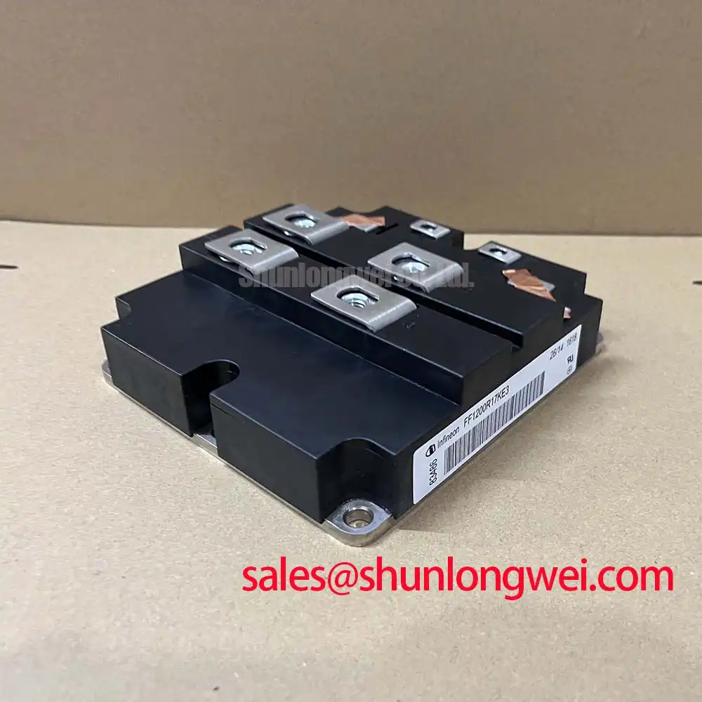
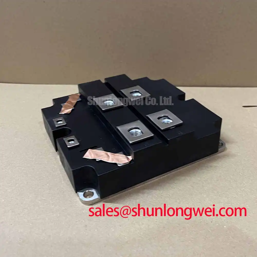
The FF1200R17KE3 is a high-power 1700V IGBT module engineered for exceptional current handling and operational reliability in demanding high-voltage applications. Its core specifications — 1700V | 1200A | Tvj op 150°C — establish a foundation for robust power system design. Key engineering benefits include superior thermal performance under load and a high-density power footprint. This module addresses the critical challenge of managing thermal dissipation in high-current systems, enabling more reliable and compact inverter designs. For high-power converters requiring proven reliability and substantial current headroom, the FF1200R17KE3 provides a robust, thermally manageable solution.
Key Parameter Overview
Decoding the Specs for Enhanced Thermal Reliability
The technical specifications of the FF1200R17KE3 are tailored for high-stress industrial and renewable energy applications. The parameters below highlight the module's capacity for managing high current and voltage with a focus on thermal stability. Each value is critical for system modeling, heatsink design, and ensuring long-term operational integrity.
| Parameter | Symbol | Condition | Value | Unit |
|---|---|---|---|---|
| Collector-Emitter Voltage | VCES | Tvj = 25°C | 1700 | V |
| Continuous Collector Current | IC | TC = 80°C, Tvj max = 175°C | 1200 | A |
| Collector-Emitter Saturation Voltage | VCEsat | IC = 1200A, VGE = 15V, Tvj = 25°C | 2.15 (typ.) | V |
| Gate-Emitter Threshold Voltage | VGE(th) | IC = 48.0 mA, VCE = VGE, Tvj = 25°C | 5.8 (5.0...6.5) | V |
| Thermal Resistance, Junction to Case | Rth(j-c) | per IGBT | 0.021 | K/W |
| Total Power Dissipation | Ptot | TC = 25°C, Tvj max = 175°C | 7150 | W |
| Operating Junction Temperature | Tvj op | -40 to +150 | °C |
Download the FF1200R17KE3 datasheet for detailed specifications and performance curves.
Application Scenarios & Value
Achieving System-Level Benefits in Megawatt Wind Turbine Converters
The FF1200R17KE3 is optimally deployed in systems where high current density and long-term reliability are non-negotiable. What is the primary benefit of its robust thermal design? Enhanced operational lifetime by minimizing thermal stress on the semiconductor junction. A prime example is in multi-megawatt wind turbine converters, a core component of modern grid infrastructure. In this scenario, engineers face the challenge of designing a power conversion stage that can operate continuously for decades in fluctuating environmental conditions, from calm breezes to full-gale winds.
The module's substantial 1200A nominal current rating provides the necessary capacity to handle peak power generation, while its low thermal resistance (Rth(j-c)) is critical for efficiently transferring waste heat away from the IGBT chip. This allows for a more compact and cost-effective heatsink design, directly impacting the overall size and bill of materials for the entire inverter cabinet. By ensuring the junction temperature remains within safe limits even under heavy load, the FF1200R17KE3 directly contributes to the converter's availability and reduces the likelihood of costly, unscheduled maintenance. While this module is engineered for very high power levels, for systems with lower current demands but similar voltage requirements, the related FF800R17KE3 offers a collector current of 800A.
Technical Deep Dive
A Closer Look at the Thermal Pathway for Long-Term Reliability
The reliability of a high-power module like the FF1200R17KE3 is fundamentally linked to its ability to manage heat. The key parameter governing this is the thermal resistance from junction to case, Rth(j-c). This value represents the opposition to heat flowing from the active semiconductor chip to the module's baseplate. To understand its importance, think of thermal resistance as the narrowness of a pipeline; a lower Rth(j-c) value is analogous to a wider pipe, allowing a greater volume of heat to be evacuated quickly and efficiently. This module's low thermal resistance is a testament to its internal construction, which prioritizes a direct and unimpeded thermal path.
This design consideration is critical for preventing the IGBT junction temperature from exceeding its maximum operating limit of 150°C. Effective heat removal is the first line of defense against accelerated aging and premature failure. For system designers, a lower thermal resistance provides more headroom in the thermal budget, potentially allowing for higher switching frequencies, increased output power, or operation in higher ambient temperatures without compromising the system's target lifespan.
Frequently Asked Questions (FAQ)
How does the FF1200R17KE3's thermal resistance directly impact system design and heatsink selection?
The low thermal resistance (Rth(j-c)) of 0.021 K/W means that for every watt of power dissipated, the IGBT junction temperature will only rise 0.021°C above the case temperature. This high efficiency in heat transfer allows engineers to specify smaller, lighter, and more cost-effective heatsinks while still maintaining the junction temperature well within its safe operating area. It directly translates to higher overall system power density.
What are the primary considerations when operating the FF1200R17KE3 at its nominal 1200A current?
Operating at 1200A requires a carefully engineered thermal management system. The main focus should be on minimizing the thermal resistance of the entire path from the module's case to the ambient air. This involves selecting a high-performance Thermal Interface Material (TIM) and a heatsink (air or liquid-cooled) appropriately sized for the calculated power losses, which are a function of the VCEsat and switching characteristics.
Is the 1700V blocking voltage of the FF1200R17KE3 suitable for applications connected to 690V AC lines?
Yes, a 1700V rating is the industry standard for power converters connected to 690V AC lines. This provides the necessary voltage margin to safely handle the DC-link voltage (typically around 1000-1100Vdc) as well as any voltage overshoots that occur during the fast switching of inductive loads, ensuring robust performance in common industrial Variable Frequency Drive (VFD) and renewable energy applications.
Strategic Advantage
Enabling the Next Generation of High-Power Conversion
The deployment of robust, high-current IGBT modules like the FF1200R17KE3 is a critical enabler for major industry trends in energy and automation. In the renewable energy sector, the push for more powerful wind turbines and utility-scale solar farms requires power electronics capable of handling megawatt-level loads with high availability. This module provides the foundational switching capability for the inverters at the heart of these systems. Similarly, in heavy industry, efficiency standards and the move towards electrification demand more powerful and reliable motor drives. The FF1200R17KE3 equips engineers with a component built to withstand the rigorous demands of these strategic markets, facilitating the development of more efficient and powerful next-generation systems. For further information on the manufacturer's technology, visit the Infineon corporate website.