

Content last revised on September 27, 2026
Preventing Spurious Faults: Insulation Barrier Integrity and Guidelines for FZ2400R17HP4_B29
Begin incoming inspection with the module fully isolated, protected against ESD, and identified against the equipment bill of materials before applying any test voltage. Confirm the marked collector, emitter, and gate connections against the original converter documentation, then record cold-state resistance and diode-mode readings as a reference for later fault analysis. Do not infer a damaged junction from one multimeter result alone; compare the complete terminal pattern with a known-good reference and the manufacturer’s applicable test conditions.
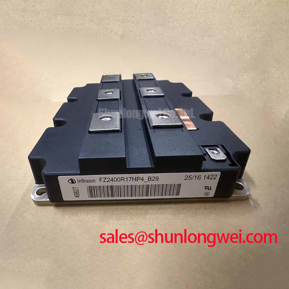
FZ2400R17HP4_B29 is an Infineon IGBT module specified for a 1700 V collector-emitter voltage, a 2400 A rated collector current under the specified datasheet conditions, and a maximum operating junction temperature of 150 °C. The stated junction-to-case thermal resistance is 0.010 K/W per switch. These ratings must be assessed under their applicable datasheet conditions and against the converter’s actual DC-link voltage, switching current, cooling arrangement, and protection settings.
| Parameter | Specification |
|---|---|
| Manufacturer | Infineon |
| Product type | IGBT module |
| Collector-emitter voltage | 1700 V |
| Rated collector current | 2400 A under the specified datasheet conditions |
| Maximum operating junction temperature | 150 °C |
| Junction-to-case thermal resistance | 0.010 K/W per switch |
Isolation integrity is a system-level verification task. A reinforced galvanic barrier, common-mode transient immunity, and any insulation withstand value must be confirmed from the applicable module datasheet and the gate-driver documentation rather than assumed from the voltage class. For a wind turbine full-scale converter, inspect the gate-driver isolation path, fiber or control interface, auxiliary supply isolation, creepage, clearance, contamination control, and chassis bonding as one assembly. The module itself cannot independently claim compliance with the complete converter’s EMC or safety certification.
When a gate fault appears intermittently, disconnect the power stage and inspect the isolated driver output with the module unenergized. Check whether the gate-emitter waveform is clean at the driver terminals and again at the module terminals. A difference between these points may indicate parasitic inductance, common-mode coupling, grounding interaction, or an interface connection problem. Designers should validate the complete gate loop during switching tests, including turn-on and turn-off ringing, before approving the replacement assembly.
💡 Bench Tip: Keep the module, test leads, and operator at the same ESD control potential, and record cold-state terminal readings before cleaning, tightening, or applying any external bias.
FZ2400R17HP4_B29 Thermal-Electrical Optimization: Thermal Interface and Practical Tuning
The specified 0.010 K/W per switch RthJC describes the junction-to-case thermal path, not the complete junction-to-coolant path. Before mounting, inspect the cooler and module base for contamination, burrs, local high spots, and visible distortion. The thermal interface material should be applied consistently according to its own supplier instructions. Thickness, spread, voids, baseplate flatness, and mounting sequence are design and assembly considerations, not additional official electrical specifications for this model.
Use a controlled, cross-pattern tightening sequence appropriate to the selected hardware and heatsink. The final torque must come from the module mounting documentation, fastener grade, and heatsink design. After assembly, verify that the cooler contacts the base evenly and that the interface material has not been displaced into an uneven ridge. Thermal imaging during a controlled load test can help identify imbalance, but the measured temperature must be interpreted with sensor placement, emissivity, coolant or airflow conditions, and switching duty in mind.
Electrical tuning should begin with the complete gate-driver network rather than with the module in isolation. Gate resistance, driver current, local decoupling, return-path inductance, and the physical separation between power and control loops all influence switching behavior. A suggested gate damping value is only a typical starting point for bench tuning; the final value should be selected from measured gate-emitter waveforms and switching-loss results.
Desaturation protection, short-circuit response, and soft turn-off must be coordinated with the actual driver and control platform. Sub-microsecond protection targets, where used, are system design considerations, not confirmed specifications for this product page. Engineers should verify detection delay, blanking behavior, fault propagation, and the energy absorbed during a controlled turn-off using the relevant driver documentation and oscilloscope measurements. Fast-acting semiconductor fuses should also be coordinated through their published I²t data, prospective fault current, and the converter’s documented short-circuit withstand capability.
Assembly Integrity and Layout Architecture: Turn-Off Overshoot Control for FZ2400R17HP4_B29
During turn-off testing, measure the collector-emitter waveform directly at the module power terminals with a suitably rated probe arrangement that minimizes added loop area. The voltage peak is influenced by DC-link voltage, commutation-loop stray inductance, and current change rate. This relationship explains why a visually short busbar can still produce excessive overshoot when the return path is asymmetric or when the probe connection adds inductance.
For a high-current converter, a symmetrical laminated or planar busbar arrangement is a design consideration for reducing unequal current paths. The target parasitic inductance must be derived from the actual switching current, allowable voltage margin, bus structure, snubber location, and measured transient response. Do not treat a generic inductance target as an official parameter of FZ2400R17HP4_B29. Snubber capacitance and damping should be selected from measured energy, ringing frequency, dielectric stress, pulse-current capability, and thermal results.
Long motor or generator cables can behave as transmission lines. Reflected waves may raise the voltage seen at the motor or generator terminals, especially when cable impedance, termination, switching edge rate, and cable length interact unfavorably. A filter, dv/dt network, or output reactor may be considered where the converter topology and equipment specification require it. The integrator should verify the actual peak voltage at both the load and module terminals rather than relying on the nominal DC-link value.
For practical fault isolation, compare the phase-leg waveforms under the same load and switching command. An imbalance may arise from busbar geometry, driver timing, current sharing, sensor placement, or a connection defect, so the measurement should include gate-emitter voltage, collector-emitter voltage, phase current, and driver supply behavior. The FF45017ME4 page can be consulted as a reference for another device, not as evidence of replacement compatibility. Electrical, mechanical, thermal, and control compatibility must be verified by the system designer.
FZ2400R17HP4_B29 Circuit Protection and Reliability: Voltage Margin and Environmental Review
The official 1700 V VCES rating is not a permission to operate a converter at that voltage under every switching condition. The engineering review should include steady DC-link voltage, regeneration events, line disturbances, control overshoot, cable effects, snubber tolerance, and the measured collector-emitter peak. For a multi-megawatt offshore or onshore wind turbine full-scale converter, these conditions should be checked at the highest credible operating temperature and at the relevant grid and generator fault states.
Cosmic-ray effects, terrestrial neutron exposure, altitude influence, single-event burnout, and FIT estimates require application-specific reliability data and an authoritative test or field source. No universal failure-rate figure or altitude derating value should be assigned to this module without the applicable Infineon reliability documentation and the converter manufacturer’s qualification basis. As a design consideration, engineers should evaluate DC-bus headroom conservatively and confirm the result through the specified voltage class, switching transient measurements, environmental profile, and protection coordination.
For an installation exposed to salt, humidity, dust, or condensation, review enclosure sealing, contamination level, creepage, clearance, conformal protection around associated circuitry, and service procedures. These factors belong to the equipment design and cannot be certified by the IGBT module alone. The technical discussion at Resonant Topologies in Home Appliances provides an additional topology reference for comparing switching paths and transient behavior. Infineon’s Automotive Qualified Power Modules page should not be treated as qualification evidence for this specific industrial module.
Before energizing a repaired converter, verify gate polarity, isolation behavior, cooling contact, fuse coordination, interlock operation, and current-sensor direction. During controlled commissioning, verify the measured switching voltage at the module terminals. Record the baseline results so future service work can distinguish a power-device issue from a driver, busbar, cooling, or system-control condition.