Content last revised on January 17, 2026
Infineon FZ1000R16KF4 | Robust 1600V IGBT for High-Power Chopper Applications
The Infineon FZ1000R16KF4 is an industry-proven high-power IGBT module designed for exceptional reliability and efficiency in demanding chopper and DC-DC converter applications. Engineered for systems requiring robust power handling and superior thermal performance, this module delivers the stability needed for critical industrial, renewable energy, and traction systems. It is a cornerstone component for designers seeking a balance of high current capability, voltage resilience, and long-term operational endurance.
Key Performance Characteristics at a Glance
| Parameter | Value |
|---|---|
| Collector-Emitter Voltage (VCES) | 1600 V |
| Continuous Collector Current (IC) @ TC=80°C | 1000 A |
| Collector-Emitter Saturation Voltage (VCE(sat)) @ IC=1000A, Tvj=125°C | 2.20 V (Typ.) |
| Total Power Dissipation (Ptot) @ TC=25°C | 5350 W |
| Short Circuit Withstand Time (tSC) | 10 µs |
| Isolation Voltage (Visol) | 3400 V (RMS, 50Hz) |
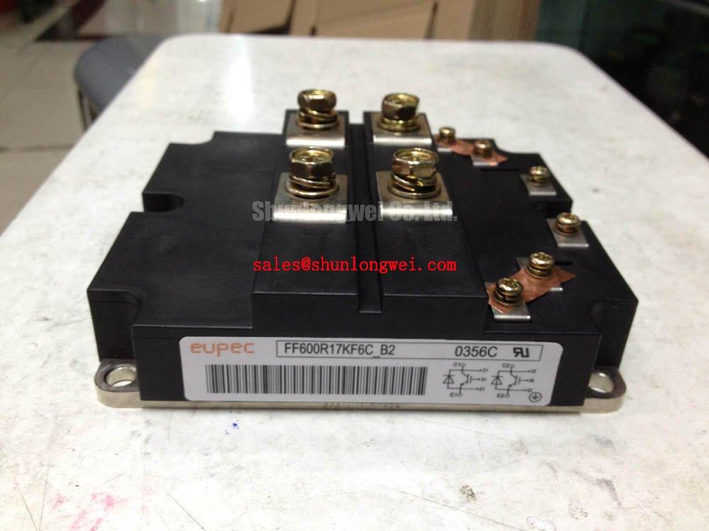
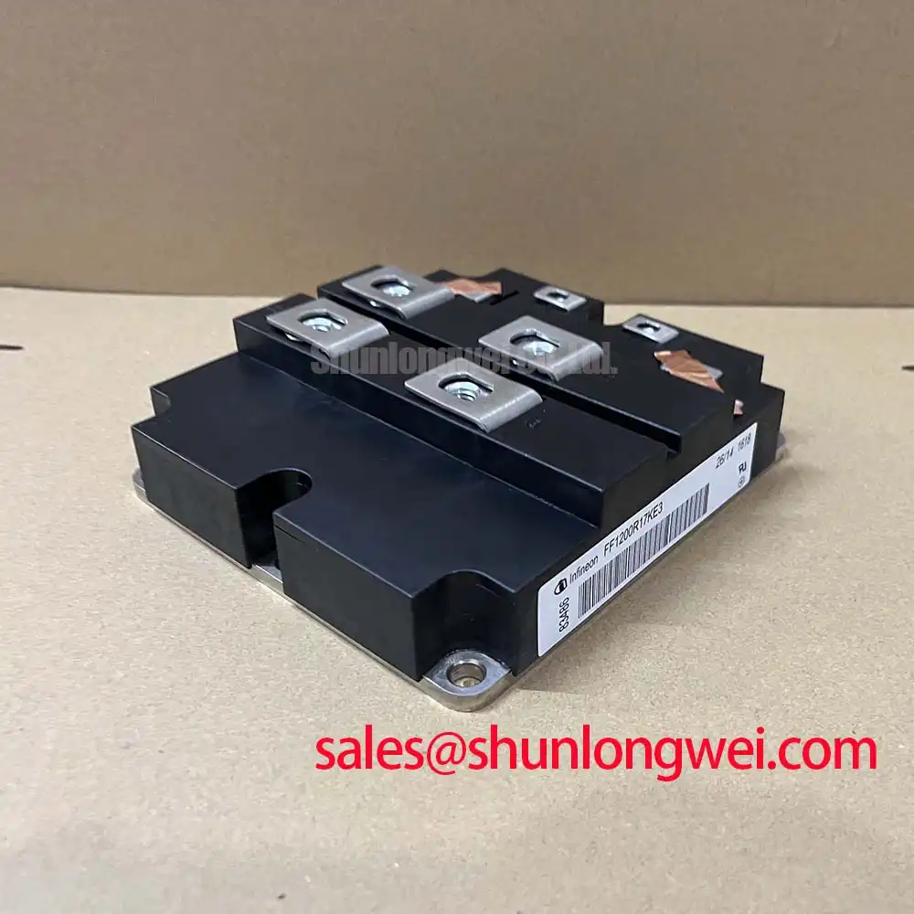
| Package Type | IHV B |
Technical Deep Dive: The Engineering Behind the FZ1000R16KF4
The robust performance of the Infineon FZ1000R16KF4 stems from two core design pillars: advanced silicon technology and superior packaging. The module utilizes Infineon's mature and highly reliable Trench/Field-Stop IGBT technology. This chip design provides an optimized trade-off between conduction losses, represented by a low VCE(sat), and switching losses. The result is minimized power dissipation during both on-state and transitions, which directly contributes to higher system efficiency and reduced thermal management requirements.
Equally important is the module's construction. Housed in the standard IHV B package, it features an AlSiC baseplate with an AlN substrate. This combination offers excellent thermal conductivity and a coefficient of thermal expansion (CTE) well-matched to the silicon chips. This synergy drastically improves thermal cycling and power cycling capability, ensuring mechanical integrity and a long service life even in applications with frequent temperature fluctuations, such as braking choppers.
Application Scenarios & Value Proposition
The FZ1000R16KF4 is not a general-purpose switch; it is a specialist engineered for specific high-power challenges:
- Braking Choppers for VFDs: In high-power Variable Frequency Drives (VFDs) for cranes, elevators, or downhill conveyors, the module reliably dissipates immense regenerative energy from the motor. Its high current rating and robust Safe Operating Area (SOA) ensure it can handle the intense, cyclical pulses of braking operations without degradation.
- Industrial DC-DC Converters: For applications like large-scale battery chargers, industrial welding, or induction heating, the module's 1600V rating provides a significant safety margin. Its low conduction losses are critical for maximizing the efficiency of the power conversion stage, reducing operational costs over the system's lifetime.
- Renewable Energy Systems: In large solar or wind power converters, this module can be used in DC bus voltage regulators or auxiliary power circuits. Its proven reliability is essential for infrastructure-grade equipment where uptime and long-term stability are paramount.
Strategic Advantage in Mature System Designs
In an era focused on the latest SiC and GaN technologies, the FZ1000R16KF4 holds a strategic position as a workhorse component. For systems operating in the medium frequency range (up to ~10 kHz), its performance-to-cost ratio is exceptional. The technology is mature, its operational characteristics are well-documented, and its reliability is field-proven across millions of hours. This makes it a low-risk, high-value choice for upgrading existing high-power platforms or designing new systems where durability and cost-effectiveness are the primary engineering drivers. It stands as a testament to how optimized silicon IGBT modules remain the backbone of industrial power electronics.
Frequently Asked Engineering Questions (FAQ)
1. What are the key considerations for the gate drive design for the FZ1000R16KF4?
A standard gate voltage of ±15V is recommended. Given its 1000A rating, a high-current gate driver with low output impedance is crucial to provide the peak current required for fast, clean switching. It is also vital to minimize inductance in the gate-emitter loop to prevent voltage overshoots and oscillations. For more on this topic, explore these 5 practical tips for robust IGBT gate drive design.
2. Can these modules be paralleled for applications exceeding 1000A?
Yes, paralleling is possible but requires careful engineering. The positive temperature coefficient of VCE(sat) inherent in this IGBT technology aids in thermal balancing. However, designers must ensure symmetrical busbar layout for equal stray inductances and use individual gate resistors to prevent parasitic oscillations between modules. Meticulous mechanical and electrical symmetry is key to successful current sharing.
For further design support or to discuss your specific application requirements for the FZ1000R16KF4, please do not hesitate to contact our technical team.