


Content last revised on February 1, 2026
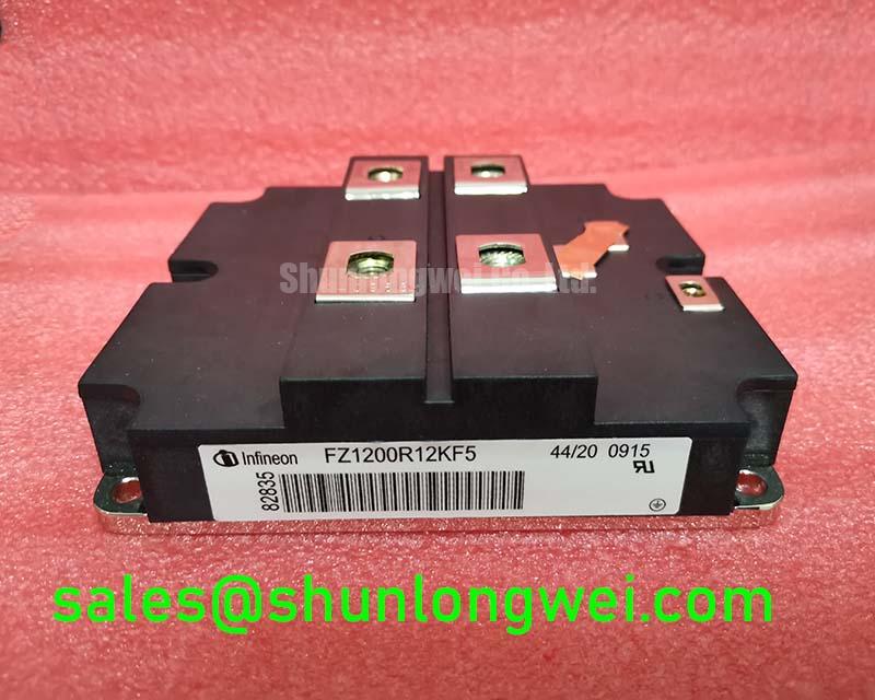
FZ1200R12KF5 | 1200V 1200A Single Switch IGBT Module
An In-Depth Engineering Review for Power System Design
Engineered for High-Frequency Efficiency in Megawatt-Scale Converters
The Infineon FZ1200R12KF5 is a high-power 1200V/1200A IGBT module designed to deliver superior efficiency in demanding high-frequency power conversion applications. With core specifications of 1200V | 1200A | VCE(sat) 1.90V (typ.), this module provides two key engineering benefits: minimized total power losses and enhanced thermal performance. It directly addresses the challenge of balancing high power density with operational efficiency in modern inverter and converter designs. Best fit for high-power industrial drives and renewable energy systems, the FZ1200R12KF5's architecture enables higher switching frequencies without significant efficiency penalties.
Application Scenarios & Value
System-Level Benefits in Industrial Drives and Renewable Energy
The FZ1200R12KF5 is engineered for applications where efficiency and reliability are paramount. Its combination of high current handling and low switching losses makes it a strong candidate for the core of high-power Variable Frequency Drive (VFD) systems used in manufacturing, mining, and material handling. What is the primary benefit of its IGBT4 technology? Reduced total power loss, which allows for smaller heatsinks and higher power density. In a multi-megawatt wind turbine or utility-scale Solar Inverter, the module's low VCE(sat) directly translates to lower conduction losses and improved annual energy production (AEP). This efficiency is critical for grid-tied converters that must operate continuously under varying load conditions. For systems requiring a different current rating within the same voltage class, the related FZ900R12KF5 offers a 900A alternative.
Key Parameter Overview
Decoding the Specs for Efficient Power Conversion
The technical specifications of the FZ1200R12KF5 are tailored for robust, high-efficiency performance. The parameters below highlight its capabilities in managing high electrical and thermal loads. Each value is a critical input for system-level simulations, particularly for predicting losses and designing effective thermal management solutions.
| Parameter | Symbol | Condition | Value |
|---|---|---|---|
| IGBT, Inverter - Collector-Emitter Characteristics | |||
| Collector-Emitter Voltage | VCES | VGE = 0V, Tvj = 25°C | 1200 V |
| Collector Current, Continuous | IC nom | TC = 100°C, Tvj max = 150°C | 1200 A |
| Collector-Emitter Saturation Voltage | VCE sat | IC = 1200A, VGE = 15V, Tvj = 25°C | 1.90 V (typ.) |
| IGBT, Inverter - Switching Characteristics | |||
| Turn-on Energy | Eon | IC = 1200A, VCE = 600V, VGE = ±15V, RG = 1.1 Ω, Tvj = 125°C | 175 mJ (typ.) |
| Turn-off Energy | Eoff | 215 mJ (typ.) | |
| Short Circuit Withstand Time | tpsc | VGE ≤ 15V, VCC ≤ 800V, Tvj max = 150°C | 10 µs |
| Thermal & Mechanical Characteristics | |||
| Thermal Resistance, Junction to Case | RthJC | per IGBT | 0.018 K/W |
| Max. Junction Temperature | Tvj max | 150 °C | |
Download the FZ1200R12KF5 datasheet for detailed specifications and performance curves.
Frequently Asked Questions (FAQ)
How does the TrenchSTOP™ IGBT4 technology in the FZ1200R12KF5 benefit high-frequency applications?The TrenchSTOP™ IGBT4 technology is specifically optimized to reduce the trade-off between conduction losses (VCE(sat)) and switching losses (Eon/Eoff). For designers, this means the module can be operated at higher frequencies—for example, in a modern VFD—to reduce the size of magnetic components like inductors and transformers, without incurring the severe efficiency penalty seen in older IGBT generations. This allows for a more compact and cost-effective overall system design.
What is the engineering significance of the 10 µs short-circuit withstand time?A short-circuit withstand time of 10 microseconds provides a critical safety margin for the power system. In the event of a fault, such as a motor winding short or a DC bus failure, this rating guarantees the IGBT can survive the immense current stress for up to 10 µs. This gives the gate drive and system-level protection circuits sufficient time to detect the fault and safely shut down the device, preventing a catastrophic failure of the module and protecting the entire inverter.
Industry Insights & Strategic Advantage
Meeting the Demands of Electrification and Grid Modernization
The transition towards industrial automation and renewable energy sources creates a clear demand for power components that offer higher efficiency and power density. The FZ1200R12KF5, with its IGBT4 technology, is well-positioned to meet these needs. Regulations and market pressures are pushing for smaller, more efficient power converters. The module's performance directly supports this trend by enabling higher switching frequencies, which in turn reduces the size and cost of passive components. For designers of systems like Commercial Agricultural Vehicles (CAV) or grid-tied energy storage systems, leveraging this module can lead to a more competitive end-product that meets evolving energy efficiency standards and reliability expectations.
To discuss the specific requirements of your high-power conversion project, or to inquire about procurement, please contact our technical sales team for an engineering-level consultation.