

Content last revised on September 13, 2026
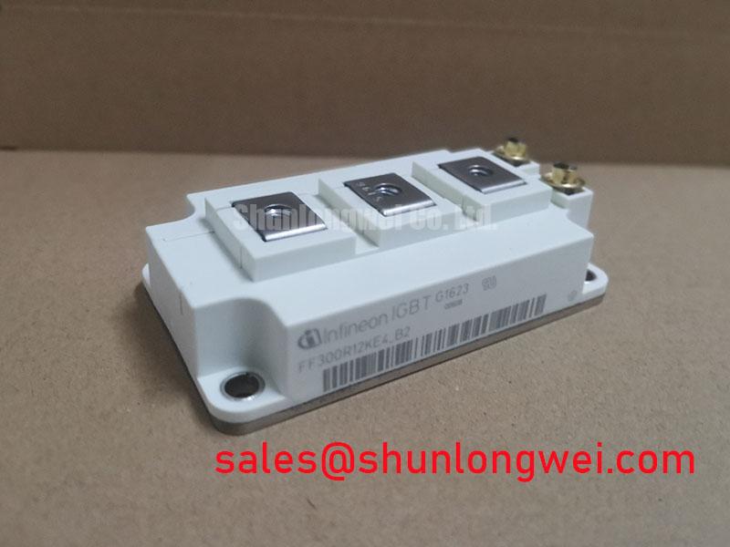
Infineon FF300R12KE4_B2 1200 V 300 A IGBT Module
Begin the service check with the equipment isolated, then verify the module marking, inspect the baseplate and terminals, and compare the nameplate limits with the drive documentation. The Infineon FF300R12KE4_B2 is specified as a 1200 V, 300 A IGBT Module in a module package. These are official product parameters supplied for identification and initial application screening; switching, thermal, isolation, and protection limits must be confirmed against the applicable manufacturer documentation before energizing a repaired drive.
| Parameter | Specified value | Engineering identity |
|---|---|---|
| Manufacturer | Infineon | Official product identification |
| Model | FF300R12KE4_B2 | Official product identification |
| Voltage rating | 1200.0 V | Official Specification |
| Current rating | 300.0 A | Official Specification |
| Package | Module | Official physical parameter |
Benchtop Waveform Tuning: Mitigating Stress via Thermal Interface Material Thickness Control on FF300R12KE4_B2
Before connecting the DC bus, check that the heatsink mounting surface is clean, flat, and free from burrs that could distort the module baseplate. Thermal interface material should cover the active contact area evenly without folds, dry zones, or trapped contamination. The thickness is a system integration variable rather than an official FF300R12KE4_B2 rating. Designers should select the material and application method from the heatsink flatness, pressure distribution, thermal resistance target, and supplier instructions.
A practical workshop method is to place the module on the prepared heatsink without tightening, confirm that the baseplate sits naturally, and start the mounting screws in a diagonal sequence. Bring the fasteners down progressively in a cross pattern so that the interface material spreads rather than being pushed toward one edge. Final torque must follow the applicable mechanical documentation for the module, fastener, and heatsink assembly. Do not infer a device-specific torque from a general M5 guideline.
When a thermal image shows an uneven temperature field, do not treat the hottest point as proof of semiconductor damage. Recheck fan direction, heatsink fouling, contact pressure, interface coverage, and current balance. A cold-state electrical inspection and a controlled low-energy switching test can help separate a thermal interface problem from a gate-drive or commutation problem.
Keep the gate-drive wiring physically separated from high-current commutation paths where practical. The gate resistor, driver return, and emitter reference should be arranged to reduce shared impedance and common-mode ground bounce. A negative turn-off bias may be considered only when it is supported by the driver design and the relevant device documentation; the actual value remains system-determined and must be validated during switching tests.
Assembly Integrity & Layout Architecture: Implementing Symmetrical Busbar Geometry for FF300R12KE4_B2
At the bench, verify every power and control terminal against the original drive schematic rather than relying on physical symmetry. Record terminal identity, polarity, and the intended gate-drive return before attaching the busbar or driver harness. This is especially important when a replacement assembly has been modified by previous service work.
For high-current inverter layouts, a symmetrical busbar arrangement is a Design Consideration for reducing unequal stray inductance and uneven current paths. Keep the forward and return conductors close enough to reduce loop area, while preserving the creepage and clearance required by the DC-link voltage, pollution environment, insulation system, and applicable safety standard. The exact distances are determined by the complete assembly, not by the module current rating alone.
Dynamic current sharing also depends on matched gate-loop geometry. Equal conductor length, similar routing, and a consistent driver reference can reduce timing differences between parallel switching paths. The positive temperature coefficient commonly associated with on-state voltage in IGBT operation can assist steady-state static current sharing, but it does not guarantee balanced transient current. Oscilloscope measurements should therefore examine gate-emitter behavior, collector-emitter voltage, and current during the actual switching event.
Busbar joints should be mechanically supported so that vibration does not transfer repeated stress into the module terminals. Inspect washers, clamping surfaces, and thread condition during scheduled service. Check for discoloration, fretting, or localized heating around the connection points, then retighten only according to the assembly manufacturer’s documented procedure. In a coordinated power stage, the FZ800R12KS4_B2 can be reviewed as a neutral reference for a related front-end or auxiliary position, subject to voltage, current, topology, and mechanical compatibility checks.
⚠️ Maintenance Note: Monitor contact temperature during preventive maintenance and recheck heatsink airflow after cleaning, because a secure electrical connection can still operate with inadequate cooling.
Field Diagnostics & Commissioning: Turn-Off di/dt Induced Vpeak Clamping in FF300R12KE4_B2 Topologies
During commissioning, capture the turn-off waveform at the module terminals with a measurement setup suitable for the switching environment. Probe placement, loop area, bandwidth, and reference connection can introduce readings that do not represent the actual device stress. The engineering relationship between turn-off overshoot and the commutation path can be described naturally as the DC-link voltage plus the stray inductance multiplied by current slew rate. This makes low-inductance busbar geometry, controlled gate resistance, and appropriate clamping a coordinated system task.
If the observed collector-emitter peak approaches the available voltage margin, first verify the measurement path and DC-link condition. Then inspect the commutation loop for excessive spacing, loose laminations, unexpected conductor branches, or asymmetric phase-leg routing. Designers should minimize parasitic loop inductance to suppress inductive overshoot, while the final peak-voltage margin must be verified against the actual switching waveform and the applicable device limits.
Snubber selection is also system-dependent. The capacitor, resistor, diode, or active clamp must be evaluated against switching energy, pulse repetition, damping behavior, physical placement, and thermal dissipation. Increasing capacitance without checking turn-on loss can move the stress into another part of the power stage. A failed or aging clamp should be assessed alongside the gate signal, DC-link ripple, fast fuse condition, and the semiconductor junction response.
For a field return, compare the affected phase leg with a known-good leg under controlled conditions. Look for abnormal gate ringing, delayed turn-off, unequal current rise, or a mismatch between the electrical waveform and the thermal image. These observations may indicate layout, driver, measurement, or device issues, so the diagnosis should remain evidence-based rather than assigned to one symptom alone.
FF300R12KE4_B2 Thermal-Electrical Optimization: Reliability Limits in Practical Tuning
A reliability review for this module should begin with measurable stresses: junction temperature behavior, case temperature, switching overshoot, gate-drive stability, overload duration, cooling performance, and protection response. The published 1200 V voltage rating and 300 A current rating identify the product class, but they do not independently define a complete operating point for an electric forklift traction inverter. The system integrator should verify the original drive’s DC-link voltage, modulation pattern, overload profile, cooling arrangement, and fault-clearing coordination.
High-altitude operation can change cooling performance and may also affect environmental electrical stress. Terrestrial neutron exposure and Single Event Burnout are application reliability topics that require authoritative device data, mission profile information, altitude assumptions, and statistical methodology. Without a qualified Infineon reliability source or applicable test report, a numeric FIT rate, SEB probability, lifetime in hours, or altitude derating factor should not be assigned to this product page.
Field engineers can still improve the evidence base by logging bus voltage, phase current, heatsink inlet condition, case temperature, switching frequency, fault timing, and ambient humidity during controlled operation. Examine the fast semiconductor fuse coordination using the protection study and the relevant I²t data for the complete circuit. A fuse cannot be evaluated from its nominal current alone, and a semiconductor module’s short-circuit withstand behavior must be confirmed from the applicable device documentation and gate-driver protection sequence.
In damp or seasonally cold facilities, inspect enclosure sealing, condensation control, connector condition, and deposits around high-voltage terminals. Creepage and clearance should be reviewed after contamination, coating changes, or mechanical rework. For background on IGBT operating principles and failure mechanisms, engineers may consult The Ultimate IGBT Knowledge Base. The Infineon IGBT Modules & Discretes Official Portfolio is also a relevant manufacturer resource for confirming the applicable product-family documentation.
Where a cross-reference is required, FZ3600R12HP4 may be examined as a separate Infineon module option, but any substitution decision must be based on verified electrical ratings, gate characteristics, mechanical fit, thermal impedance, protection settings, and the complete inverter qualification test.