Content last revised on June 30, 2026
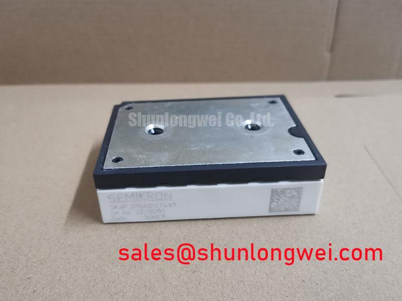
SKiiP24NAB12T4V3 | 1200V 300A IPM with Pressure Contact Technology
This SKiiP 4 IPM delivers superior operational reliability in demanding inverter systems by leveraging a solder-free pressure contact design. Featuring key specifications of 1200V | 300A | Vce(sat) 1.85V, the module offers tangible engineering benefits, including enhanced power cycling capability and simplified thermal management. It fundamentally eliminates solder fatigue, a primary failure mechanism in conventional modules, ensuring consistent performance over an extended operational lifetime. What is the benefit of its integrated CAN interface? It enables digital control and advanced diagnostics for the gate driver. For motor drives up to 110 kW requiring maximum reliability, this IPM's pressure contact technology makes it the benchmark choice.
Key Parameter Overview
Decoding the Specs for Thermal Performance and Efficiency
The technical specifications of the SKiiP24NAB12T4V3 are engineered to provide a robust foundation for high-efficiency power conversion. The parameters are grouped by function to facilitate system-level evaluation for your application.
| Parameter | Value | Conditions |
|---|---|---|
| Inverter IGBT Characteristics | ||
| Collector-Emitter Voltage (VCES) | 1200 V | Tj = 25 °C |
| Nominal DC Collector Current (ICnom) | 200 A | |
| Max. Repetitive Peak Current (ICRM) | 300 A | |
| Collector-Emitter Saturation Voltage (VCEsat) | 1.85 V (typ.) / 2.25 V (max.) | IC = 200 A, Tj = 125 °C |
| Short Circuit Withstand Time (tpsc) | 10 µs | VCC = 800 V, Tj = 150 °C |
| Inverter Diode Characteristics | ||
| Forward Voltage (VF) | 1.80 V (typ.) / 2.15 V (max.) | IF = 200 A, Tj = 125 °C |
| Peak Reverse Recovery Current (IrrM) | 310 A (typ.) | IF = 200 A, VR = 600 V, Tj = 125 °C |
| Thermal & Mechanical Characteristics | ||
| Thermal Resistance, Junction to Case (Rth(j-c)) | 0.14 °C/W (per IGBT) | |
| Max. Junction Temperature (Tj,max) | 175 °C | |
| Operating Temperature (Tj,op) | -40 to 150 °C | |
Application Scenarios & Value
Enhancing System Reliability in Industrial Drives and Power Conversion
The SKiiP24NAB12T4V3 is engineered for applications where operational uptime and low maintenance are paramount. Its primary value is demonstrated in high-performance Variable Frequency Drive (VFD) systems, servo drives, and solar or UPS inverters.
Consider the engineering challenge of a heavy-duty industrial conveyor system that undergoes hundreds of start/stop cycles per hour. These cycles induce significant thermal swings within the power module, placing immense stress on internal solder and wire bond connections. Over time, this leads to material fatigue and eventual failure, causing costly production halts. The SKiiP24NAB12T4V3 directly mitigates this risk through its pressure contact design. By eliminating solder layers between the substrate and the heatsink, it dramatically improves the module's Power Cycling Capability. This design integrity translates into a longer service life and a lower Total Cost of Ownership (TCO) for the end equipment. While the SKiiP24NAB12T4V3 is optimized for applications around 110 kW, systems requiring higher power output could evaluate the SKiiP35NAB12T4V1 which offers a higher current rating within the same technology family.
Frequently Asked Questions
Engineering Questions on the SKiiP24NAB12T4V3
How does the solder-free pressure contact system in the SKiiP24NAB12T4V3 improve reliability compared to standard soldered modules?
The pressure contact system eliminates the baseplate and the solder layers that attach the ceramic substrate to it. These solder layers are a common point of failure in conventional modules due to fatigue from repeated thermal expansion and contraction. By creating a direct, reliable pressure connection to the heatsink, the design enhances the module's operational lifetime, particularly in applications with high thermal cycling.
What is the practical benefit of the integrated CAN interface for the gate driver?
The integrated CAN interface allows for digital communication between the system's central controller and the IPM. This enables precise control over gate drive parameters and provides a channel for advanced diagnostics, such as reporting fault conditions, monitoring temperature, and tracking operational status. This simplifies system integration and allows for more sophisticated, data-driven control and predictive maintenance strategies.
The datasheet specifies Trench 4 IGBTs. How does this impact inverter efficiency and thermal design?
SEMIKRON's Trench 4 (T4) IGBT technology represents a specific generation of silicon design optimized for a balance between low collector-emitter saturation voltage (VCEsat) and reduced switching losses. A lower VCEsat minimizes power lost as heat during the on-state (conduction), while optimized switching characteristics reduce losses during the on/off transitions. For an engineer, this translates to higher overall inverter efficiency and less waste heat to manage, which can lead to the specification of a smaller, more cost-effective heatsink, a critical factor in modern thermal management.
Technical Deep Dive
A Closer Look at the Solder-Free Pressure Contact Design for Long-Term Reliability
The defining feature of the SKiiP24NAB12T4V3 is the use of Semikron's SKiiP® Technology, a sophisticated pressure contact system that sets it apart from conventional power modules. Instead of a copper baseplate with soldered substrates, this design uses a precisely engineered spring system to apply uniform pressure, pressing the active ceramic substrates directly onto the system's heatsink. This architecture is a direct response to the primary wear-out mechanisms in high-power electronics.
Think of a conventional soldered module like a road with asphalt patches. Over time, temperature changes create cracks in the patches, degrading the connection. The pressure contact system is like a perfectly milled, single piece of stone roadway—it expands and contracts uniformly, maintaining a robust and unbroken connection for the life of the system. This inherent robustness dramatically enhances the module's ability to withstand thermo-mechanical stress, making it an ideal choice for applications where long-term reliability is non-negotiable.
Furthermore, this design offers a significant thermal advantage. The elimination of the baseplate and solder layers removes two interfaces from the thermal path. This is akin to removing unnecessary insulation from a cooling pipe; it creates a more direct, unimpeded path for heat to escape from the silicon chip to the heatsink. The result is a lower thermal resistance (Rth(j-c)), enabling the IGBT module to run cooler at a given load or handle higher power levels without exceeding temperature limits, thus improving both performance and system longevity.
For engineering teams evaluating this module, it is recommended to review the specific mounting and heatsink flatness requirements in the datasheet to fully leverage the performance benefits of its advanced pressure contact system.