

Content last revised on October 10, 2026
Cold-Start Backlight Checks for the Sharp LQ121S1DG81
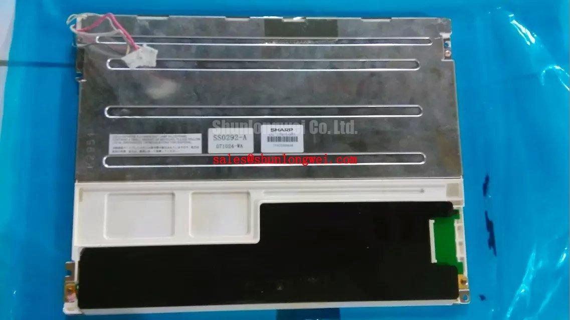
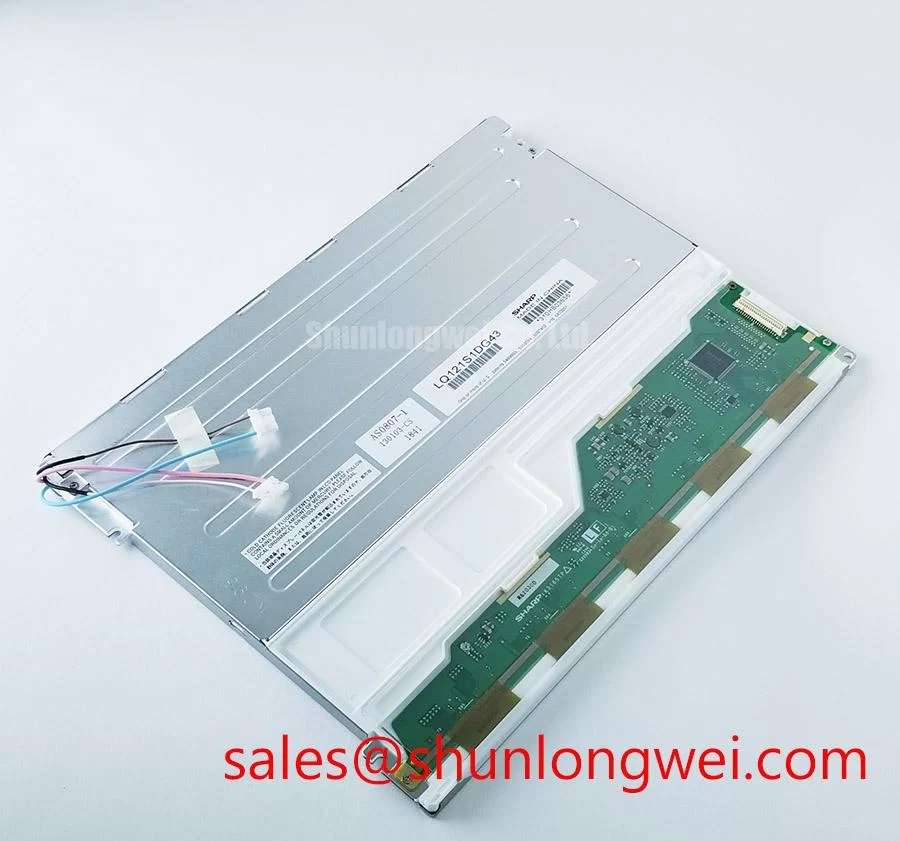
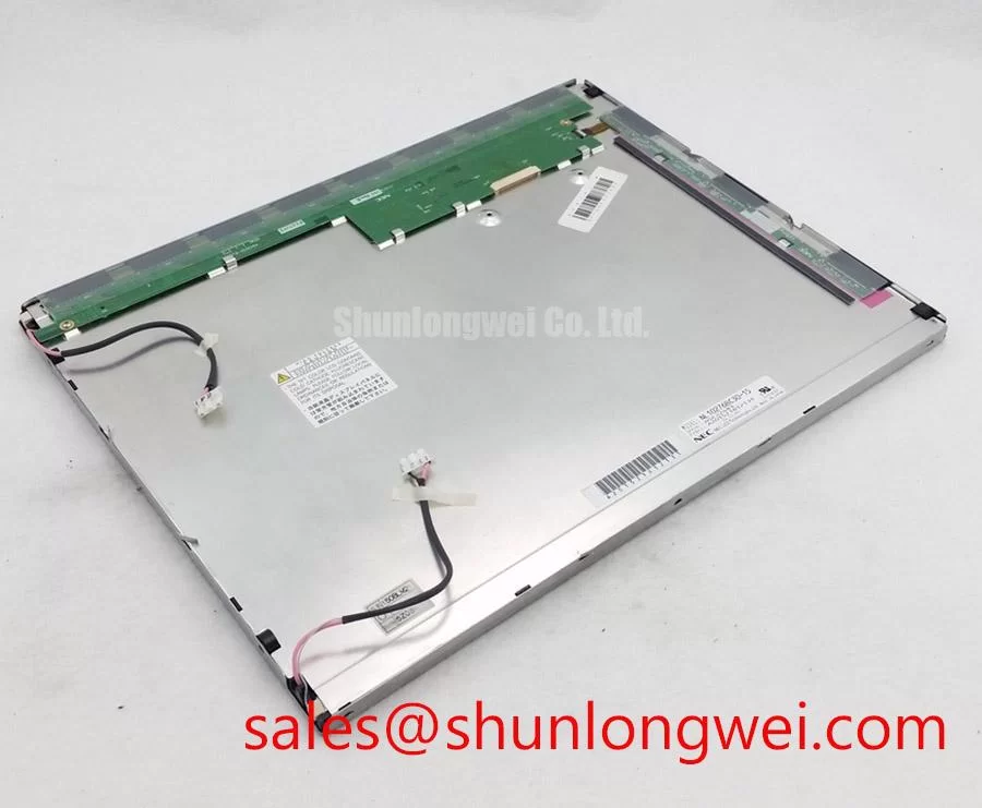
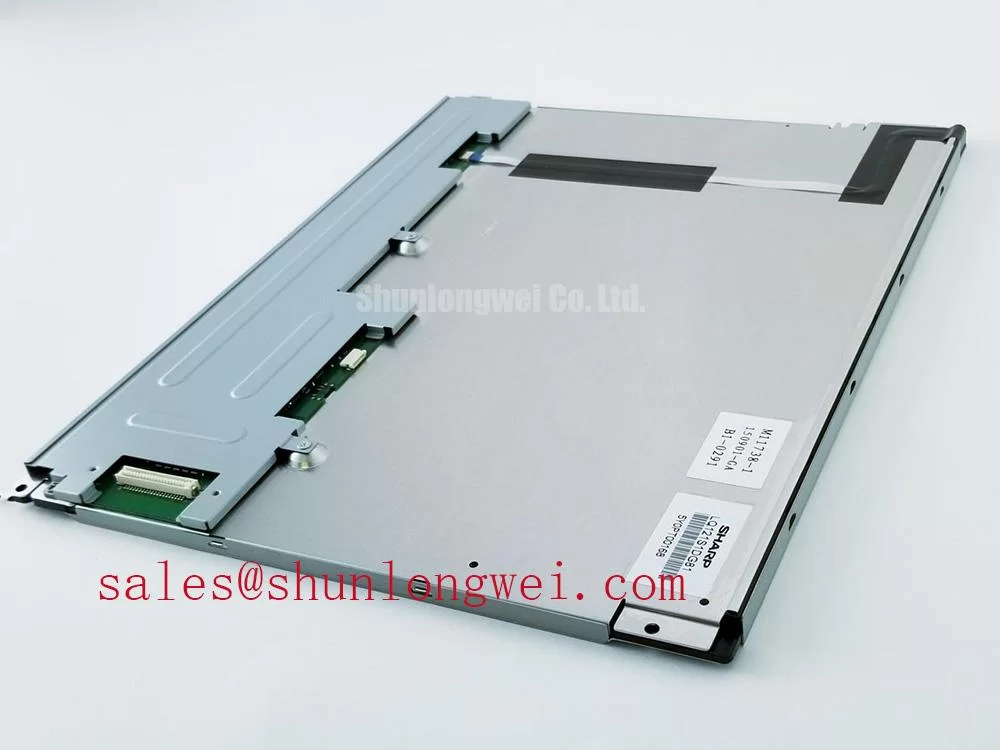
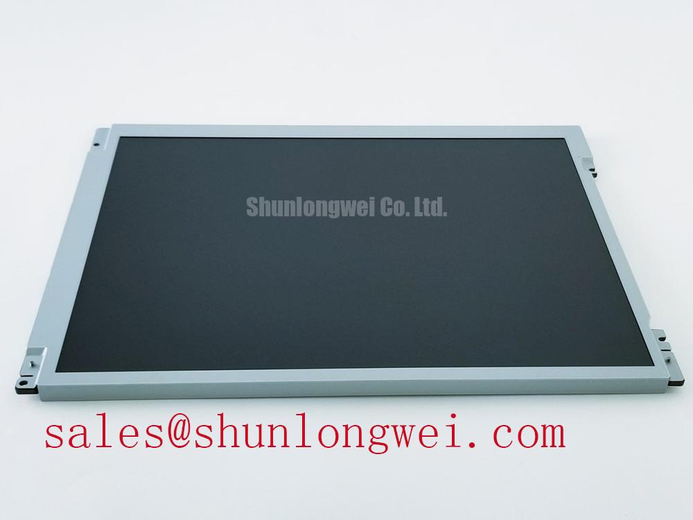
When a CNC operator panel remains dark after the controller starts, first separate the display signal fault from the backlight ignition fault by checking whether image content is faintly visible under an external inspection light. The replacement part is the Sharp LQ121S1DG81, identified as a TFT-LCD active matrix color display module for industrial display and HMI integration.
The available product identity confirms the manufacturer as Sharp. Values such as supply voltage, optical dimensions, pixel resolution, connector assignment, and backlight architecture should be matched with the original panel documentation before installation.
| Manufacturer | Sharp |
| Model | LQ121S1DG81 |
| Display type | TFT-LCD active matrix color display module |
| Application context | Industrial display and HMI integration |
A cold-start test should observe the first several seconds of illumination, not just the steady-state picture. A CCFL-equipped assembly may require a high-voltage striking event, whereas an LED assembly depends on the installed constant-current backlight circuit. The figures sometimes used for CCFL ignition, LED PWM dimming, or backlight lifetime are system-level values and must not be assigned to the LQ121S1DG81 without a matching Sharp specification.
For a suspected inverter fault, inspect the backlight connector, cable seating, and driver fault output while monitoring the panel image separately. Disconnect power before handling backlight connections; energized CCFL inverter measurements require appropriately rated equipment and qualified personnel. A protection shutdown can be triggered by an open lamp path, excessive current, connector arcing, or a driver-side control error. Replacing the panel without recording these conditions can leave the original fault in the machine.
When the equipment uses an LED retrofit or an external backlight controller, evaluate the current regulation, startup behavior, open-load response, short-circuit response, and dimming control as one circuit. A nominally compatible connector does not establish electrical compatibility. Engineers evaluating a related front-end or display power arrangement may also review LQ10D41 as a separate Sharp display solution, while confirming its actual role in the target system.
Optical Stack Stability During Continuous Full-Duty Operation
Full-screen white testing is the quickest way to expose uneven illumination, localized bright zones, dark corners, and contamination marks on an industrial replacement display. Run white, black, red, green, and blue test fields at controlled brightness, then compare the panel with the known-good unit from the same machine. This process helps distinguish panel pixel defects from backlight distribution problems.
The LQ121S1DG81 should be handled as a complete TFT-LCD display module rather than as a bare optical sheet assembly. Do not assume the diffuser film, prism structure, light guide, or thermal spreader construction from the model number alone. If the existing enclosure uses narrow metal rails near the display edges, check for uneven compression, bent retaining clips, and contact marks before transferring the replacement into the chassis.
A practical design consideration is to keep heat sources away from the optical stack and to provide a uniform mechanical support surface. Localized heating can produce temporary brightness variation or long-term optical change, but the result depends on the enclosure, backlight power, airflow, and mounting pressure. A stated 50,000-hour half-brightness figure is a backlight test target associated with defined current, temperature, and duty conditions; it is not an automatic lifetime specification for this Sharp module.
For strong ambient lighting, inspect the front surface at the actual operator viewing angle. Anti-glare or anti-reflection performance must be confirmed from the supplied panel construction or the original equipment specification. Do not add a film or bonded cover lens without checking optical clarity, surface reflection, touch sensitivity, and mechanical clearance.
💡 Bench Tip: Use ESD protection and engage the display flex connector squarely before locking it; an uneven latch can create intermittent image faults that appear only when the enclosure is closed.
Temperature Evaluation and Signal Integrity in Factory Environments
Cold-start behavior should be assessed separately from normal operating response when a CNC panel or robot teach pendant is exposed to a wide temperature cycle. Liquid crystal response can slow at low temperature, while connector materials, sealing surfaces, and the metal enclosure expand at different rates. Record image refresh behavior, gray transitions, flicker, and intermittent lines during the temperature transition rather than judging the panel from a single static frame.
The commonly discussed range of −30°C to +85°C must not be treated as an official LQ121S1DG81 operating rating unless it appears in the applicable Sharp documentation. A system qualification envelope must respect the documented limits of the panel, cable, controller, adhesive materials, and enclosure; testing them together does not override individual component ratings. Sharp’s industrial display resources, including Sharp Devices Europe Industrial Display Solutions and the Sharp Display Solutions Official Portal, provide useful reference points for industrial display evaluation.
High-frequency servo drives and switching power supplies can disturb the display through cable coupling, grounding paths, or an unsuitable signal return. Route display wiring away from noisy power conductors where the machine layout allows, maintain a continuous return path, and inspect the shield termination at both the panel and controller ends. The final EMC result belongs to the complete equipment assembly, not to the LCD module alone.
If the interface uses differential signaling, verify the actual connector pinout, pair assignment, termination arrangement, and timing requirements from the original system documentation. A 100 ohm differential target or a 50 ps skew budget may be appropriate for a particular high-speed interface design, but neither value should be assigned to this model without confirmation. Use an oscilloscope at the panel-side connection when a missing image, unstable sync, or color corruption suggests a signal-integrity problem.
For a broader service reference covering TFT display selection, interface behavior, and common integration errors, consult The Ultimate Guide to Industrial TFT-LCD Technology. A same-size or same-resolution alternative should be compared by connector position, active area, optical stack, mounting pattern, and controller compatibility rather than by diagonal size alone. The LQ104V1LG81 can be considered as a separate comparison point during cross-model evaluation, subject to a complete mechanical and electrical match.
Mechanical Clearance and Front-Bezel Installation
Before fastening the LQ121S1DG81 into a heavy industrial metal enclosure, place the module in the cutout without tightening and check the bezel opening, connector clearance, cable bend path, and contact points around the active area. A bezel that presses against the glass or frame can create dark-field mura, uneven illumination, or intermittent operation after thermal cycling.
Use the original mounting pattern as the primary reference. M3 fasteners and cross-pattern tightening are common mechanical practices, but a torque value such as 0.35 to 0.45 N·m is a general installation consideration rather than a confirmed Sharp specification for this model. The correct value depends on the bracket material, screw length, washer arrangement, thread engagement, and the panel manufacturer’s mechanical drawing.
When a front cover or touch overlay is part of the equipment, confirm that it does not transfer point pressure into the display surface. Capacitive or resistive touch performance, glove operation, and wet-finger response belong to the complete touch assembly and controller. They should be tested with the actual cover, cable routing, grounding arrangement, and operator gloves used in service.
PWM backlight control should also be evaluated at the system level. A proposed frequency range such as 200 Hz to 1 kHz may be suitable for some driver designs, but the LQ121S1DG81 product identity alone does not establish a required PWM frequency or duty-cycle response. Check for visible flicker directly; a camera test can reveal modulation artifacts, but these depend on camera settings and do not necessarily represent human-visible flicker. Observe acoustic noise near the driver, and confirm that brightness changes remain stable across the intended control range.
After installation, repeat the full-screen color test with the bezel tightened, then flex the external cable gently at the service strain relief while monitoring the image. Any change in brightness, lines, or synchronization calls for connector, cable, grounding, and enclosure-clearance inspection before the machine returns to production.