
Content last revised on September 10, 2026
NL12876BC26-32D Inspection and Verification
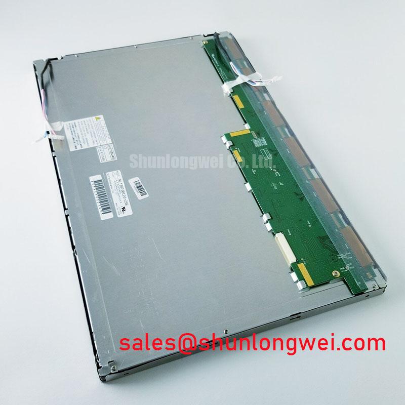
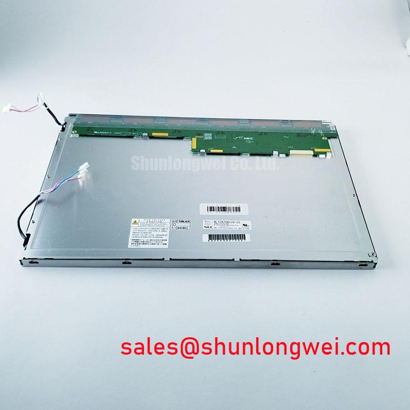
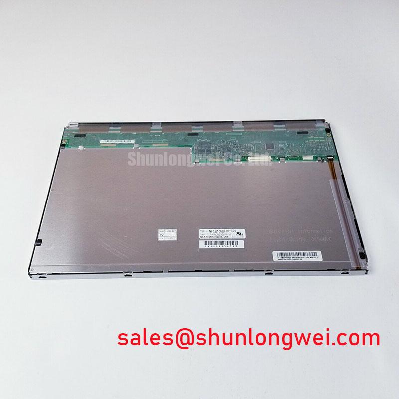
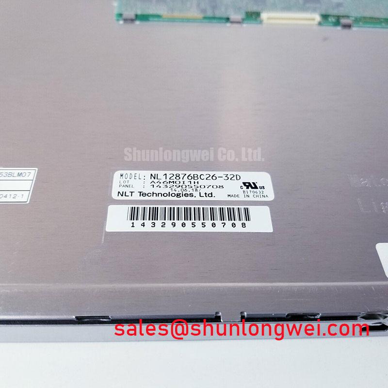
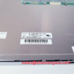
Before reconnecting NL12876BC26-32D, isolate system power, inspect the TFT-LCD display module connector latch, and compare the panel label with the original equipment record before any electrical test. The verified factory identification is NEC, with the product classified as an Industrial Grade LCD/HMI Panel in a TFT-LCD Display Module package. The available official factory record confirms specification verification, but does not provide electrical supply ratings, interface pin assignments, optical values, operating temperature limits, mechanical dimensions, backlight data, or mounting limits. Those values must be verified against the original NEC panel documentation and the host equipment schematic.
For black screen, dim image, intermittent picture, or unstable startup investigation, first separate panel symptoms from host-board symptoms. Confirm that the display cable is fully seated, that its locking mechanism is engaged, and that the host controller is providing the intended video stream. A panel that remains dark can be associated with an absent or unstable backlight supply, an incorrect enable sequence, a damaged cable path, or a controller-side signal issue. A visible but distorted image can point to an interface mapping, grounding, or signal-integrity condition. These observations require measurement against a known-good equipment path rather than diagnosis from appearance alone.
⚠️ Field Alert: Disconnect system power and allow stored energy to discharge before inserting or removing the display connector, because live connector handling can disturb signal and supply pins.
Assessing Localized Thermal Gradients and Optical Color Shift
Localized heating at a panel edge should be treated as an enclosure and backlight-system assessment, not as an inherent characteristic claimed for NL12876BC26-32D. The supplied factory information does not specify the panel’s backlight technology, thermal path, brightness rating, illumination lifetime, or permissible edge temperature. It is therefore inappropriate to assign an LED lifetime figure, an L70 or B50 rating, or a specific optical-material mechanism to this NEC module.
As a Design Consideration, technicians should inspect the display cavity for concentrated heat sources near the panel perimeter, blocked airflow, poorly supported interface boards, and contact between the module and nearby power components. When a display shows nonuniform brightness or a localized color change, compare the thermal condition of the affected installation with an equivalent known-good assembly. The aim is to determine whether the condition follows the panel, the enclosure, the controller, or an adjacent heat source.
Aluminum rails, chassis heat-spreading features, and thermal interface methods must be evaluated as system-level design elements. Their suitability depends on the original equipment’s panel support locations, clearance requirements, enclosure geometry, and the manufacturer’s mounting guidance. A rigid rail placed where the original bezel does not support the panel can introduce mechanical stress rather than solve a heat problem.
Brightness control also requires confirmation from the original circuit documentation. The available official data does not identify whether the host equipment uses PWM control, DC dimming, or another backlight control method, and it does not state an acceptable dimming frequency or duty-cycle relationship. When flicker, noise, or brightness instability is reported, engineers should probe the actual control path and compare it with the known-good host design. The investigation should include backlight enable behavior, supply stability, cable condition, and the timing relationship between video activation and illumination.
For installations where a replacement decision requires comparison with another NEC industrial display module, the NL8048AC19-13KD can be reviewed as a separate product record. Any comparison must be based on verified documentation for resolution, active area, interface, mounting geometry, power requirements, and optical performance. Similar naming, manufacturer, or product category alone does not establish interchangeability.
Assessing Display Contrast and Temperature-Related Image Changes
The official information available for NL12876BC26-32D identifies an industrial-grade TFT-LCD display module but does not confirm panel mode, viewing-angle specification, contrast ratio, response-time behavior, surface finish, anti-glare treatment, color coordinates, or luminance. No claim should therefore be made that this model uses TN, IPS, MVA, or any other liquid-crystal architecture. Likewise, no specific viewing cone, anti-glare etching method, or dynamic contrast capability can be attributed to the model without the relevant NEC documentation.
When a field unit appears washed out, changes tone after warm-up, or displays uneven grayscale, use a controlled comparison method. Allow the suspect system and a known-good system to reach comparable operating conditions, present the same static test image, and observe whether the change is tied to the panel, the video source, or the enclosure environment. A controller with an unstable reference, a cable with poor contact, or an incorrect image configuration can create visual effects that resemble panel degradation.
As a Design Consideration, long periods of static HMI imagery should be assessed at the equipment level. Persistent status bars, fixed icons, and high-contrast windows can make retained image effects more noticeable on some display technologies and configurations. The appropriate mitigation is determined by the host software, operating duty, panel documentation, and the visual requirements of the application. A screen-saver policy, controlled brightness behavior, or periodic interface refresh may be considered only where the equipment owner’s validation process permits it.
For potential use in surgical navigation or ultrasound diagnostic display terminals, engineers should avoid treating the industrial classification as a statement of medical-system suitability. Equipment-level requirements can involve image-quality validation, electrical safety, cleaning compatibility, enclosure sealing, system risk management, and applicable regulatory review. The module’s factory classification is Industrial Grade LCD/HMI Panel; any use in a specialized display terminal remains subject to the complete equipment design and its required approvals.
Backlight decay curves, illumination maintenance figures, and quantified operating-hour predictions are not included in the provided official factory record. Rather than assigning a lifetime number, maintenance teams can document present brightness uniformity, startup behavior, thermal condition, and repeatability over the equipment’s normal duty cycle. For wider context on panel selection, operating principles, and common industrial display considerations, consult The Ultimate Guide to Industrial TFT LCD Technology.
Differential-Interface Flex Routing and Signal-Integrity Assessment
The available factory information does not state the logic supply voltage, interface type, connector pin count, signal standard, differential impedance requirement, power-on timing, or JEIDA and VESA mapping for NL12876BC26-32D. It would be unsafe to assume a 3.3 V or 5.0 V supply, LVDS signaling, a 100-ohm differential path, or a particular data mapping solely from the product category. The system integrator should verify the required supply voltage, interface assignments, and sequencing requirements from the original panel documentation.
During an emergency display replacement, preserve the original cable routing and inspect every flex section for folds, abrasion, sharp bends, damaged shielding, and partial latch engagement. Flexible cables frequently fail at points of repeated motion, at unsupported exits from the chassis, or near connectors that receive side loading during service. A cable can look intact while producing intermittent image loss under vibration or when the enclosure is closed.
If the panel powers but shows split images, vertical artifacts, unstable color, or intermittent synchronization, inspect the whole signal path before assigning fault to the module. Verify the host controller configuration, the continuity and seating of the cable assembly, chassis grounding strategy, and whether the installed display is matched to the original equipment interface. Where high-speed differential signaling is confirmed by the original design documents, routing continuity and controlled impedance are important Design Considerations for suppressing reflections and timing disturbance. The final acceptance decision should come from waveform and functional tests on the actual system.
Power sequencing must also follow the original equipment requirements. White screen behavior, residual image during shutdown, or a picture that appears only after repeated cycling can be associated with the host supply order, enable control, controller initialization, or cable condition. Do not create a substitute timing profile from generic panel practices. Capture the sequence from a verified working unit where possible, then validate the replacement assembly using the host equipment’s documented procedure.
The panel should be considered one part of a complete display chain that includes the controller board, cable assembly, power source, illumination subsystem, mechanical support, and protective front construction. Where another NEC display solution is being evaluated within that chain, the NL128102BC28-04 should be reviewed using its own verified specifications. It should not be treated as an electrically or mechanically interchangeable companion without a documented comparison.
Chassis Fastening and Optical Uniformity Assessment
The official factory record supplied for NL12876BC26-32D does not specify mounting-hole size, fastener type, torque value, bezel dimensions, panel thickness, compression limits, vibration rating, shock rating, or permissible chassis flatness. A specific M3 torque range cannot be presented as an NEC requirement for this model. Installation teams must obtain the panel drawing and the host mechanical drawing before selecting hardware or defining a tightening process.
As a Design Consideration, uneven fastening can introduce local stress into a display assembly and may be associated with optical nonuniformity, pressure marks, or intermittent connector loading. Installers should use the original mounting locations, maintain even support around the chassis, and tighten fasteners in a balanced sequence where the equipment procedure calls for it. The correct torque is determined by the actual screw size, thread engagement, bracket material, panel support design, and manufacturer documentation.
Before final closure, inspect whether the bezel or retaining frame touches the active display area, whether cable strain relief is present, and whether the panel can move under normal equipment vibration. The connector should not be used as a structural support point. If an enclosure applies pressure near a cable exit, adjust the routing and support arrangement according to the equipment design rather than forcing the cable into a tighter bend.
Cold-start image lag and slower visual transitions can be influenced by ambient conditions, panel technology, host initialization, and illumination behavior. The supplied data does not state a low-temperature operating range or a response-time specification for this NEC module, so no sub-zero operating claim can be assigned. If equipment is deployed in low-temperature environments, technicians should test the complete assembly at the intended condition and verify image stability, startup repeatability, connector retention, and enclosure stress before release.
Optical bonding, front-window sealing, moisture resistance, and dust exclusion are properties of the completed display assembly unless explicitly specified for the panel itself. The factory information here identifies a TFT-LCD Display Module, not a finished sealed monitor. When the module is fitted behind a protective window, the integrator should verify clearance, adhesive compatibility, serviceability, condensation control, and image quality after assembly. This preserves a clear boundary between the NEC panel and the performance of the finished equipment.