Content last revised on September 29, 2026
Assembly Integrity and Layout Architecture: Braking Circuit Evaluation for SEMX453GB176HD
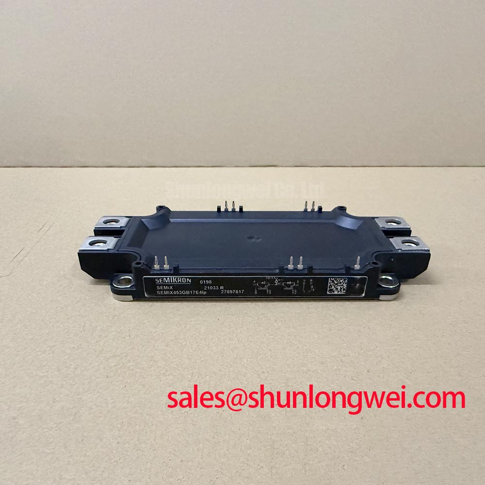
With the drive isolated and its DC link verified discharged, compare the installed module’s terminal layout with the equipment schematic before connecting SEMX453GB176HD. The supplied official specifications identify it as a Semikron IGBT module rated at 1200 V and 450 A (Official Specifications). Those ratings establish electrical boundaries; they do not establish its terminal assignment, internal circuit, or suitability as a braking chopper. Confirm those details against the original equipment documentation before wiring it into a heavy-duty variable frequency AC motor drive.
During motor deceleration, regenerated energy raises DC-link voltage unless the drive has a path to absorb or return it. If the equipment uses a braking chopper, its switching device and resistor must be evaluated as a system: expected deceleration energy, resistor pulse capability, chopper control, cooling, and permitted DC-link voltage all matter. As a Design Consideration, keep the high-current connection between the DC link, chopper, and resistor compact to limit inductive overshoot, while maintaining the clearances required by the equipment design. The 1200 V module rating alone cannot determine braking-resistor size or validate a chopper topology.
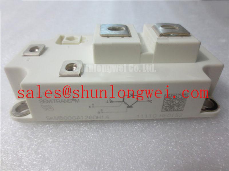
For a repair-material comparison, SKM75GB07E3 is a separate Semikron part to assess against the equipment’s electrical, mechanical, and gate-drive requirements, not a confirmed drop-in replacement for SEMX453GB176HD. Check the original bill of materials and connection drawing rather than treating a shared manufacturer name as evidence of compatibility.
SEMX453GB176HD Thermal-Electrical Optimization: Limiting Gate Voltage Spikes
Probe gate-to-emitter voltage at the module connection during controlled switching tests, with measurement equipment appropriate to the drive’s potential and transient environment. Rapid voltage change at an adjacent switching node can couple through device capacitance and disturb an off-state gate. This is a Design Consideration, not a claim that a particular capacitance or gate-voltage limit has been specified for SEMX453GB176HD. Compare the measured waveform with the gate-driver limits and the applicable module documentation before changing the driver.
Where a complementary switch could turn on unintentionally, designers should evaluate low-impedance gate return paths and, where supported by the chosen driver and module limits, an active Miller clamp. Negative off-state bias is another system-dependent option, not a prescribed setting for this part. Route gate-drive and power-current paths to reduce shared inductance; assess any RC snubber against measured switching transients and its own dissipation. 💡 Pro Tip: Keep the opposing power paths geometrically balanced to limit turn-off overshoot, then verify peak-voltage margin with switching measurements.
Do not infer phase-angle control or line-frequency ripple requirements from the module’s ratings. Those behaviors depend on the surrounding converter topology and DC-link network. For broader context on how a different power-device technology affects three-phase conversion, see The 1200 V CoolSiC™ MOSFET Advantage in Three-Phase Power Conversion; its MOSFET discussion is not a specification for this IGBT module.
Preventing Spurious Faults: Thermal Interface Inspection for SEMX453GB176HD
Inspect the heatsink contact area and mounting surfaces before installing the module. Remove contamination, check for raised burrs, and apply thermal interface material according to the selected material’s instructions and the applicable module mounting guidance. Uniform coverage and controlled mounting matter more than assuming a universal paste thickness: the supplied SEMX453GB176HD specifications do not state a thickness, baseplate curvature, screw sequence, or torque. As a Design Consideration, tighten fasteners progressively in the sequence specified by the mounting documentation so that contact pressure is not concentrated at one edge.
If thermal trips appear after service, review cooling airflow, heatsink seating, interface coverage, sensor placement, and the drive’s operating record before assigning a cause. A temperature alarm does not, by itself, identify a defective module. Disconnect power and verify the DC link is discharged before loosening a module or its connections.
Packaging and cooling approaches differ across Semikron-Danfoss product families. The manufacturer’s SKiiP® Technology information is useful background on integrated power-assembly design, but SKiiP construction or mounting details must not be attributed to SEMX453GB176HD without its specific documentation.
Field Diagnostics and Commissioning: Current Distribution in SEMX453GB176HD Topologies
Before energizing a repaired assembly, document cold-state terminal measurements and compare them with the equipment service procedure and a known-good circuit path, where available. Check power connections for looseness, inspect gate connections for routing differences, and confirm that each driver channel responds as intended. A static measurement can identify an apparent short or open path, but it cannot establish switching balance under load.
If the equipment parallels modules, review both steady-state and dynamic sharing rather than relying on the 450 A rating as a current allowance for each position. A positive temperature coefficient of on-state voltage can assist static sharing under relevant operating conditions, but the supplied specifications do not confirm a coefficient or its operating range for this part. Treat that mechanism as a Design Consideration; verify actual current distribution and temperatures in the assembled system.
During staged commissioning, compare gate waveforms and branch-current measurements at corresponding positions. Unequal gate-loop impedance, DC-link path inductance, cooling, or connection resistance may contribute to imbalance; no single symptom proves one cause. The system engineer should establish acceptable current, temperature, and voltage margins from the complete module documentation and measured operating conditions. The supplied ratings do not specify a surge-current limit or a junction-temperature recovery interval, so neither should be assumed when assessing repeated overload or braking events.