


Content last revised on June 29, 2026
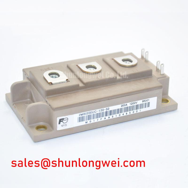
2MBI200UC-120 Fuji Electric 1200V 200A Dual IGBT Module
How do power electronics engineers maximize switching efficiency without incurring massive thermal penalties in high-current industrial drives? The Fuji Electric 2MBI200UC-120, a dual-pack IGBT module rated at 1200V and 200A, provides the answer by striking a robust equilibrium between conduction and switching losses. It features a continuous collector current of 200A (at Tc=80°C) and a max power dissipation of 1040W per device. Designed to solve common challenges in Variable Frequency Drives (VFDs) and grid-tied systems, it offers engineers a predictable thermal roadmap. What is the primary benefit of its low stray inductance? Easing snubber circuit requirements and reducing voltage overshoot.
Frequently Asked Questions
Addressing Crucial Gate Drive and Thermal Performance Questions
How does the collector-emitter saturation voltage (VCE(sat)) of the 2MBI200UC-120 affect thermal design at high currents?
The module features a nominal VCE(sat) of 2.7V (at 25°C, 200A). This low on-state voltage drop minimizes static conduction losses. To visualize this, think of the on-state voltage drop like a narrow toll booth on a highway: a lower toll (lower VCE(sat)) allows traffic (current) to pass through with much less friction (heat generation). This makes thermal design for the cooling fins significantly simpler and reduces the overall heatsink size.
What strategies should be employed to mitigate voltage spikes during fast turn-off phases?
At high switching speeds, stray inductance within the module packaging can trigger catastrophic voltage overshoots. To prevent this, design a low-inductance busbar layout and utilize a robust gate drive that incorporates active clamping. This ensures the module operates well within its 1200V Reverse Bias Safe Operating Area (RBSOA).
Why is the junction-to-case thermal resistance (Rth(j-c)) of 0.14°C/W critical for long-term reliability?
An Rth(j-c) of 0.14°C/W for the IGBT portion means that for every watt of power dissipated, the temperature difference between the silicon junction and the module's copper baseplate is only 0.14°C. This exceptional thermal path keeps the junction temperature (Tj) well below the +150°C safety threshold, dramatically improving power cycling capability and extending the system's operational lifetime under continuous thermal load. How does the U-Series design enhance efficiency? By optimizing the trade-off between conduction and switching losses.
Key Parameter Overview
Decoding the Specs for Enhanced Thermal Reliability
The technical parameters of the 2MBI200UC-120 are foundational for accurate system modeling, thermal management design, and performance validation. The table below outlines the key specifications derived from the official Fuji Electric datasheet, grouped by function to facilitate engineering evaluation.
| Absolute Maximum Ratings (Tc = 25°C unless noted) | |||
|---|---|---|---|
| Parameter | Symbol | Conditions | Value |
| Collector-Emitter Voltage | VCES | - | 1200V |
| Gate-Emitter Voltage | VGES | - | ±20V |
| Continuous Collector Current | IC | Tc = 80°C | 200A |
| Pulsed Collector Current | ICP | 1 ms | 400A |
| Max. Collector Power Dissipation | PC | 1 device | 1040W |
| Isolation Voltage | Viso | AC 1 min. | 2500V |
| Electrical Characteristics (Tj = 25°C unless noted) | |||
| Collector-Emitter Saturation Voltage | VCE(sat) | IC = 200A, VGE = 15V | 2.7V (typ.) / 3.3V (max.) |
| Gate-Emitter Threshold Voltage | VGE(th) | VCE = 20V, IC = 200mA | 5.5V to 7.5V |
| Zero Gate Voltage Collector Current | ICES | VCE = 1200V, VGE = 0V | 1.0mA (max.) |
| Thermal & Mechanical Characteristics | |||
| Thermal Resistance (Junction-to-Case) | Rth(j-c) | IGBT (1 device) | 0.14°C/W (max.) |
| Operating Junction Temperature | Tj | - | +150°C (max.) |
Download the 2MBI200UC-120 datasheet for detailed specifications and performance curves.
Technical Deep Dive
Optimizing Carrier Concentration and Minimizing Parasitic Over-voltages
Fuji Electric’s U-Series technology utilized in the 2MBI200UC-120 leverages an advanced planar-trench gate structure to optimize carrier concentration in the drift region. This architecture significantly lowers conduction losses without compromising the module's robust short-circuit ride-through capability, which is standard for heavy-duty IGBT modules.
To comprehend this technological balance, we can compare it to an efficient hydraulic system. The trench gate works like a high-flow valve that permits smooth, unimpeded fluid transfer under normal pressure (low on-state losses), yet can instantly restrict excessive flow when a line rupture occurs (robust short-circuit protection), preventing system-wide failure.
Furthermore, the layout features a Kelvin Emitter terminal configuration. This design bypasses the main power emitter's parasitic inductance, ensuring that the gate driver receives a clean control signal, which prevents spurious turn-on events triggered by fast di/dt transitions. Designers can reference the official Fuji Electric documentation for recommended gate resistance values to fine-tune turn-on delay times.
Application Scenarios & Value
Achieving System-Level Efficiency in Industrial Motor Drives
For 1200V heavy-duty industrial drives requiring optimized thermal management under 200A load, the 2MBI200UC-120 represents the most pragmatically balanced selection.
In the field of high-power industrial machinery, engineers frequently confront the challenge of severe current surges and high thermal stress during motor start-up sequences. When designing inverter stages for high-load conveyor systems, selecting a module with low stray inductance and solid thermal dissipation is paramount. By integrating the Fuji Electric 2MBI200UC-120, engineers can confidently manage motor starting currents because of the module's robust transient capability.
To ensure a safe operating margin, a thorough decoding of IGBT datasheets is recommended to verify the Safe Operating Area boundaries under typical load-shedding events. This dual module is a standard choice in several power-dense systems, including industrial UPS units, high-frequency welding power supplies, and servo drives.
When scaling systems for higher current demands, engineers may evaluate higher-tier models such as the related 2MBI200U4H-120-50 for optimized high-speed switching, or consider the 2MBI200VB-120 for newer V-Series trench technology advantages.
As a leading distributor of high-power semiconductors, we provide engineers with the precise datasheets, technical support, and authentic parts required for critical industrial projects. For pricing queries, stock availability, or detailed integration support regarding the 2MBI200UC-120, please contact our specialized technical sales team today.