


Content last revised on June 29, 2026
Mitsubishi UM150CDY-10 Datasheet, Specs & Analysis: 500V 150A IGBT Module
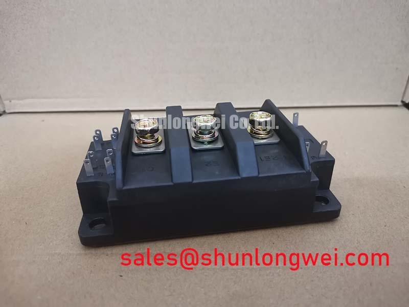
Introduction to the UM150CDY-10 IGBT Module
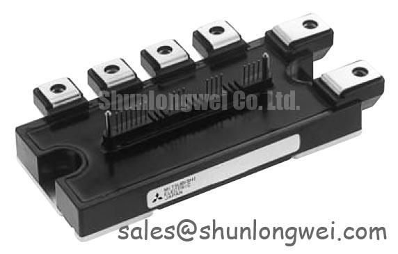
The Mitsubishi UM150CDY-10 is a high-performance single IGBT module engineered to streamline thermal design and enhance reliability in high-current switching applications. With core specifications of 500V | 150A | Rth(j-c) 0.16°C/W, this module delivers two critical engineering benefits: simplified thermal design and high power conversion flexibility. The primary advantage of its integrated insulated base is the elimination of external insulating layers, which directly reduces assembly complexity and improves the consistency of heat transfer. What is this module's main advantage? Its insulated base simplifies assembly and improves thermal transfer. For industrial chopper and drive systems on ~240V AC lines prioritizing simplified assembly and thermal reliability, the UM150CDY-10 is an engineered choice.
Application Scenarios & Value
System-Level Benefits in Industrial Power Conversion
The UM150CDY-10 is engineered for a range of high-power switching applications where reliability and efficient thermal performance are critical. Its characteristics make it particularly well-suited for systems where operational robustness and ease of manufacturing are key design drivers.
- Welding Power Supplies: In a high-current welding application, managing intense thermal cycles is a primary engineering challenge. The UM150CDY-10's low thermal resistance (Rth(j-c)) of 0.16°C/W provides an efficient path for heat to escape from the IGBT chip to the heatsink. Think of thermal resistance as the narrowness of a hallway for heat trying to escape a crowded room. This module's low value is like having a wide, unobstructed exit, allowing heat to flow out easily. This capability is crucial for handling the high peak currents of the welding process without exceeding the maximum junction temperature, thus enhancing the equipment's field reliability and lifespan.
- DC Motor Controllers & Choppers: For DC-DC chopper circuits and motor drives, the module's single-switch configuration offers significant design flexibility. It allows engineers to create custom power stages for applications like forklifts, industrial actuators, and other systems requiring precise Pulse-Width Modulation (PWM) control of DC power without the constraints of a pre-configured half-bridge module. What does low thermal resistance enable? It enables smaller heatsinks or higher power output reliably.
While the UM150CDY-10 is optimized for 500V systems, for applications requiring higher voltage blocking capabilities, the related CM150DY-24H offers a 1200V rating in a dual-IGBT configuration.
Key Parameter Overview
Decoding the Specs for Thermal and Electrical Robustness
The specifications of the UM150CDY-10 are tailored for robust performance in industrial power systems. The parameters below are grouped by function to aid in design evaluation. These values are extracted from the datasheet and represent performance under specified test conditions.
| Absolute Maximum Ratings (Tc=25°C unless otherwise specified) | ||
|---|---|---|
| Parameter | Symbol | Value |
| Collector-Emitter Voltage | VCES | 500 V |
| Collector Current (DC) | IC | 150 A |
| Maximum Junction Temperature | Tj | 150 °C |
| Isolation Voltage (AC, 1 minute) | Viso | 2500 Vrms |
| Electrical & Thermal Characteristics (Tj=25°C unless otherwise specified) | ||
| Collector-Emitter Saturation Voltage (Max) | VCE(sat) | 2.7 V |
| Thermal Resistance (Junction to Case) - IGBT | Rth(j-c) | 0.16 °C/W (Max) |
| Thermal Resistance (Junction to Case) - Diode | Rth(j-c) | 0.3 °C/W (Max) |
Frequently Asked Questions
Engineering Questions on the UM150CDY-10
How does the Rth(j-c) of 0.16°C/W directly impact heatsink selection and system power density?
A lower thermal resistance value signifies more efficient heat transfer away from the semiconductor junction. This superior thermal performance allows engineers to either use a smaller, more cost-effective heatsink for a given power level or to push more current through the module while maintaining a safe junction temperature. This directly contributes to a more compact and power-dense final product, a critical consideration in modern heatsink design.
What is the main engineering benefit of the "Insulated Type" design compared to a non-isolated module?
The primary benefit is the simplification of the manufacturing and assembly process. A non-isolated module requires a separate, external insulating pad (e.g., mica, silicone) and careful application of thermal grease to electrically isolate it from a grounded heatsink. This introduces variables in assembly consistency and thermal performance. The UM150CDY-10's integrated insulated base eliminates these external components and steps, reducing labor costs, improving manufacturing throughput, and ensuring a consistent, reliable Thermal Resistance path from the module to the heatsink.
Technical Deep Dive
The Engineering Advantage of the Insulated Base Design
A standout feature of the UM150CDY-10 is its "Insulated Type" construction. This design integrates a ceramic insulating layer, typically Alumina (Al2O3) or Aluminum Nitride (AlN), directly into the module's baseplate. This base is electrically isolated from the semiconductor terminals while remaining thermally conductive.
This construction provides significant engineering advantages over traditional non-isolated modules. Using a non-isolated module with a separate insulation pad is like making a sandwich with an unpredictable slice of bread in the middle—the thickness, contact pressure, and grease application can vary, affecting the overall thermal performance. The UM150CDY-10's integrated insulation is like having that layer perfectly bonded in the factory, ensuring a consistent, reliable thermal 'sandwich' every time. This eliminates the risk of assembly errors, such as forgetting the pad or damaging it during installation, which could lead to immediate electrical failure or long-term reliability issues due to poor heat dissipation.
For engineering and procurement teams, this translates into a lower total cost of ownership. While the module itself may have a different price point, the savings in assembly components (no need to source and stock separate insulators), reduced labor time, and increased production line yield provide a compelling system-level economic benefit. Furthermore, the high isolation voltage of 2500 Vrms ensures this simplified design meets rigorous safety standards for industrial equipment.
Request for Quotation
To evaluate the UM150CDY-10 for your power system design or to inquire about volume pricing and availability, please contact our technical sales team. We can provide the necessary support to help you integrate this module into your next project efficiently and reliably.