Content last revised on September 10, 2026
I2t Sub-Cycle Melting Rating & Semiconductor High-Speed Fuse Coordination
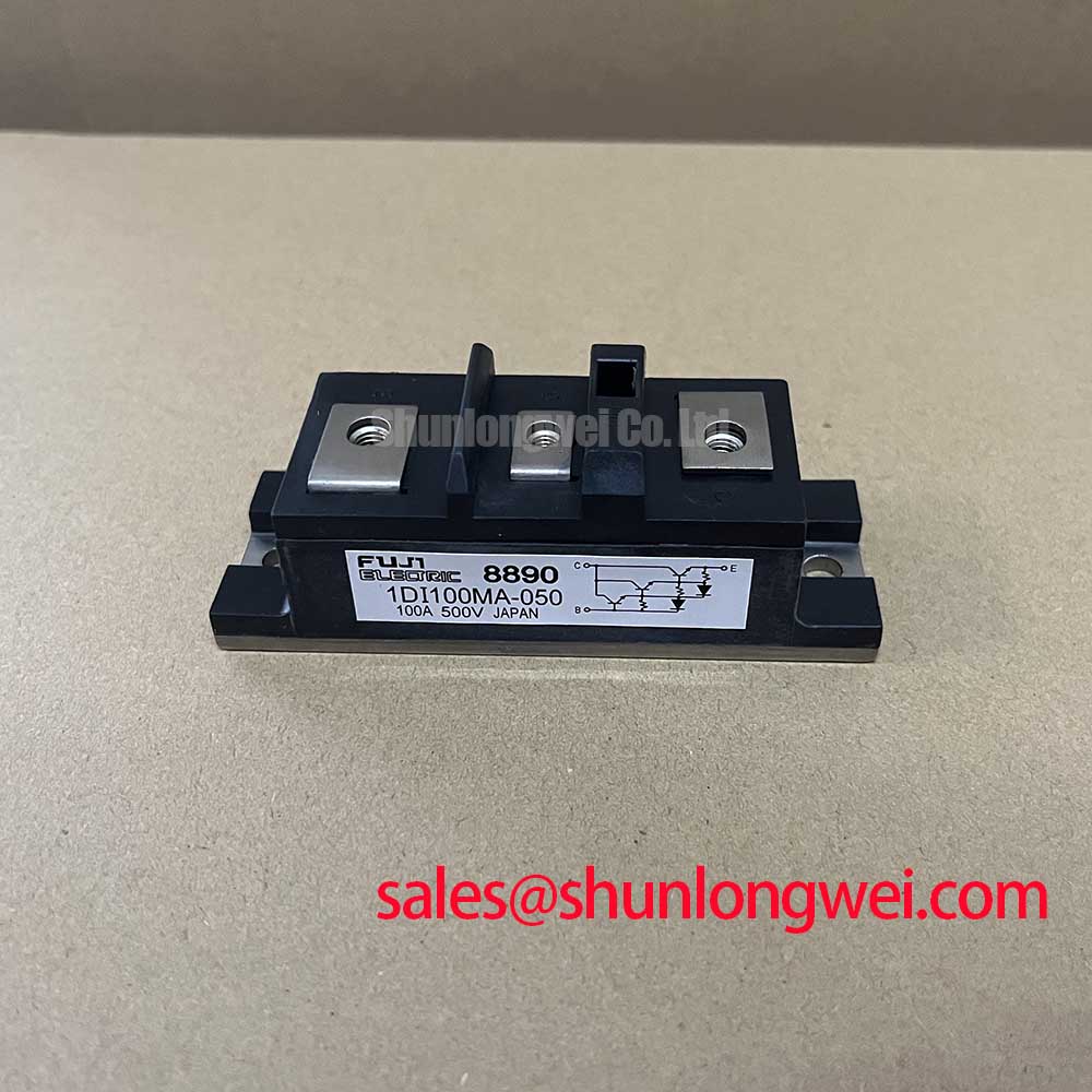
In high-current green hydrogen electrolyzer DC power rectifiers, managing catastrophic short-circuit currents is a primary design priority. The 2DI100MA-050 module from Fuji Electric is rated for a continuous collector/forward current of 100A at a case temperature of 25°C (Official Datasheet Specification) and can handle a peak collector current pulse of 200A for 1 ms (Official Datasheet Specification). When a low-impedance short circuit develops across downstream electrolyzer cell stacks, semiconductor protection relies entirely on ultra-fast semiconductor fuses clearing the fault before junction thermal limits are breached.
To establish safe fuse-module coordination, the total clearing energy (I2t) of the selected fuse must remain strictly below the short-duration thermal withstand limit of the internal silicon dies. Operating the 2DI100MA-050 within high-current electrolysis supplies requires secure busbar coupling to maintain thermal equilibrium; the module specifies an isolated baseplate mounting torque of 3.5 N·m (Official Datasheet Specification) with a physical module weight of 0.438 kg (Official Datasheet Specification). For higher potential DC bus architectures requiring expanded blocking margins beyond the 500V collector-emitter voltage (Official Datasheet Specification) rating of this unit, engineering teams often evaluate the related 2DI100A-120 for 1200V-class conversion platforms. Official module integration standards can be referenced through Fuji Electric Europe Semiconductor & Power Electronics documentation.
Pulse-Transformer Isolated Firing Circuit Design for Medium-Voltage Thyristor Modules
In industrial-grade rectifiers, gate drive isolation and control pulse integrity prevent localized hot-spot formation on the silicon substrate. The 2DI100MA-050 features a maximum gate-emitter voltage rating of ±20V (Official Datasheet Specification) and an electrical isolation voltage rating of 2500V AC for 1 minute between the terminals and the copper baseplate (Official Datasheet Specification). When switching under elevated di/dt conditions, firing circuits must provide a sharp rising edge (typically exceeding 1 A/µs, Typical Starting Point) to ensure rapid, uniform conduction across the active die area.
💡 Pro Tip: Route the Kelvin emitter auxiliary connections directly to the local driver board using tightly twisted pairs or shielded planar traces. Separating the high-current power return from the gate reference prevents parasitic loop inductance from inducing negative gate bounce, which avoids spurious turn-off transitions during high-current electrolysis surges.
Prolonged thermal and electrical stress on driver interfaces can accelerate gate dielectric degradation mechanisms, an effect extensively analyzed in studies on Negative-Bias Temperature Instability (NBTI) in Gate Dielectrics. Ensuring stable gate clamping suppresses transient overvoltages below the absolute maximum junction rating of +150°C (Official Datasheet Specification), maintaining continuous rectifying stability over long electrolyzer campaign cycles.
High-Frequency Switching Loss Dissipation in Fast-Recovery Rectifier Diodes
Thermal management within multi-megawatt green hydrogen facilities demands rigorous dissipation calculations. The 2DI100MA-050 supports a maximum collector power dissipation of 800W at 25°C case temperature (Official Datasheet Specification). During continuous operation, reverse recovery charge (Qrr) and peak reverse recovery current (IRRM) generate switching power losses during each commutation cycle, which transfer through the module baseplate to the liquid-cooled heatsink.
| Parameter | Datasheet Rating | Engineering Function |
|---|---|---|
| Collector-Emitter Voltage (VCES) | 500V | DC bus blocking voltage headroom |
| Continuous Current (IC) | 100A (TC = 25°C) | Continuous rectifier bridge forward conduction |
| Peak Pulsed Current (ICP) | 200A (1ms pulse) | Sub-cycle fault withstand capability |
| Power Dissipation (PC) | 800W | Maximum internal heat transfer capability |
| Storage Temperature (Tstg) | -40 to +125°C | Passive storage environmental boundary |
For modular multi-pulse rectifier designs requiring symmetrical dual-diode phase leg bridging across alternative rail voltages, system designers frequently incorporate the complementary 2DI100Z-140 module into upstream secondary-rectifier assemblies. Maintaining a uniform thermal interface material (TIM) layer thickness of 50–80 µm (Design Consideration) ensures reliable thermal conduction to liquid cold plates.
Saturable Reactor and Snubber Sizing to Protect Thyristor Junctions during High di/dt
Green hydrogen electrolysis loads present low dynamic impedance, making the rectifier bridge susceptible to steep turn-on current slopes (di/dt) and inductive voltage spikes during commutation. Integrating a series saturable reactor introduces non-linear inductive delay, delaying current rise until the power semiconductor has fully entered conduction. Parallel RC snubber networks (Rs and Cs) dampen voltage overshoot across the terminals, ensuring peak transient voltages remain well below the 500V maximum limit (Official Datasheet Specification).
Comprehensive root-cause diagnostics, clamping verification procedures, and field testing methodologies for power assemblies can be referenced in the Field Engineer’s Handbook. Proper damping network tuning eliminates spurious dv/dt re-triggering and protects power semiconductor junctions from localized avalanche breakdown during abrupt input line disturbances.