Content last revised on October 5, 2026
Transient Dynamics & Electrical Design: Critical Rate of Rise of Off-State Voltage on 2DI100M-050
A diode bridge does not have a gate that can be spuriously triggered by an off-state voltage transient. For 2DI100M-050, the practical transient question is whether commutation and wiring inductance produce reverse-voltage peaks within the module’s 500 V rating (Official Specification). A numerical critical voltage-rise limit is not established by the supplied specifications, so it should not be treated as a selection parameter for this part.
As a Design Consideration, inspect the existing snubber, bus connections, and wiring route before changing the bridge. A snubber intended to limit voltage overshoot must be assessed in the installed circuit: capacitor current, resistor heating, operating frequency, and measured reverse-voltage peaks all matter. A series saturable reactor, if present in the equipment, likewise belongs to the wider commutation design; its value cannot be prescribed from the bridge voltage and current ratings alone. Record waveforms under representative operating conditions and let the system design determine whether any network needs adjustment.
For a medium-frequency induction melting or hardening furnace power supply, first establish where the bridge sits in the schematic. The equipment may contain separately controlled power stages, but that does not make this diode module a firing-angle-controlled device. Fuji Electric’s power semiconductor product information provides manufacturer context; the installed circuit documentation remains necessary for terminal identification and transient assessment.
2DI100M-050 Thermal-Electrical Optimization: I2t Sub-Cycle Melting Rating Practical Tuning
The 100 A rating (Official Specification) is not a short-circuit withstand rating. Fuse coordination requires the prospective fault current, the selected fuse’s clearing characteristics, and the module’s applicable surge-current or I²t limit. No numerical I²t limit or fuse coordination table is established by the supplied module specifications. It would therefore be unsound to claim that a particular fuse guarantees protection against damage during a dead short.
| Coordination item | Evidence needed before approval |
|---|---|
| Module fault withstand | Applicable Fuji Electric surge-current and I²t data, including their stated test conditions |
| Fuse clearing performance | Manufacturer data for the exact fuse and its operating conditions |
| Available fault current | Equipment-level assessment of the supply and fault path |
| Installed thermal path | Heatsink condition, mounting instructions, and measured operating temperatures |
For maintenance, inspect the heatsink air passages for dust, check the condition of the thermal interface when the assembly is serviced, and verify terminal tightness using the applicable equipment or module documentation. Do not assign a mounting torque from bolt size alone: the module hardware, terminal construction, and heatsink arrangement must be confirmed. Compare temperatures taken at repeatable locations under comparable load before interpreting a rising trend. Maintenance note: Isolate and discharge the equipment before checking terminal connections or disturbing the thermal interface.
When reviewing a longer-term maintenance plan, keep measured temperatures, load conditions, and service observations alongside the applicable manufacturer limits rather than inferring a service-life figure from the current rating. The Power Semiconductor Selection Guide can support the broader comparison process, while the installed assembly’s documentation determines its inspection and test criteria.
Assembly Integrity & Layout Architecture: Reverse-Recovery Behavior for 2DI100M-050
Reverse recovery matters when current transfers away from a conducting diode: the resulting current and voltage waveforms can influence switching stress elsewhere in the circuit. The supplied 2DI100M-050 specifications do not state peak reverse-recovery current, recovery time, or a recovery-softness measure. Do not assign values to those characteristics or assume that another module in the family has the same behavior.
As a Design Consideration, keep the bridge’s power connections consistent with the equipment layout and investigate unexpected commutation spikes with suitably rated measurement equipment. Compare the waveform with a documented, functioning signal path where one is available. A spike may involve wiring inductance, a changed snubber, operating conditions, or interaction with another switching device; the waveform alone does not identify a single failed part. Any proposed layout change should be checked against measured peak voltage and the bridge’s official rating.
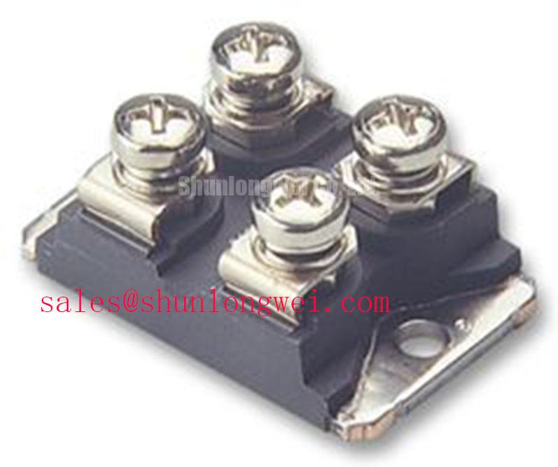
Before fitting the module, reconcile each external terminal with the equipment schematic, then confirm that the mounting surface and connection clearances suit the assembly. The 2DI100Z-140 is a separate model to compare against documented electrical ratings, terminal arrangement, and mechanical fit, not an automatic substitute. The same checks apply when reviewing 2DI100D-050C elsewhere in a power-supply parts list. Fuji Electric Europe’s semiconductor and power-electronics information offers a manufacturer channel for obtaining product documentation where more detail is needed.
Preventing Spurious Faults: Harmonic Current Injection and Line Filter Guidelines for 2DI100M-050
Firing-angle calculations belong to a controlled rectifier stage, not to the 2DI100M-050 diode bridge itself. Its 500 V and 100 A ratings (Official Specification) cannot determine an AC-to-DC transfer characteristic, displacement power factor, or reactive-power demand for a complete furnace supply. Those outcomes depend on the line arrangement, upstream impedance, connected load, and any separately controlled stage.
If line-filter heating or nuisance protection trips appear after service, compare input-current waveforms and supply conditions with the equipment’s documented operating state. Check filter connections and cooling, then assess the filter against measured current and the system designer’s requirements. Adding a filter or changing its size without examining the complete installation can shift resonances or thermal loading; component-level ratings alone cannot establish system EMC compliance.
For a repair decision, retain the distinction between a module match and a system match. Confirm the bridge’s terminal mapping and mechanical fit, verify measured voltage and current against the applicable conditions for the 500 V and 100 A official ratings, and resolve fuse, transient, and filter questions using the relevant equipment and component documentation.