


Content last revised on October 3, 2026
SKB52-08 Product Checks and Thermal Limits After a Surge
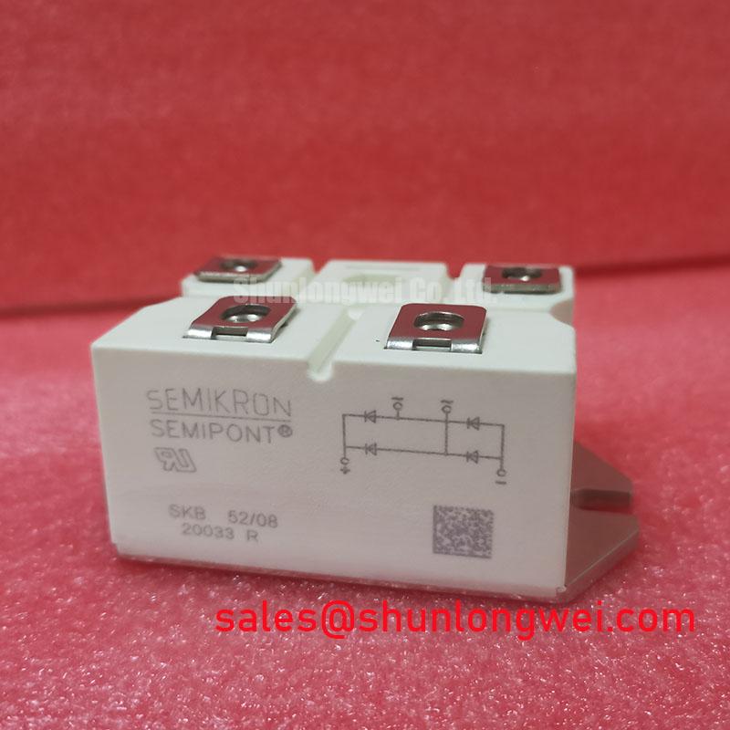
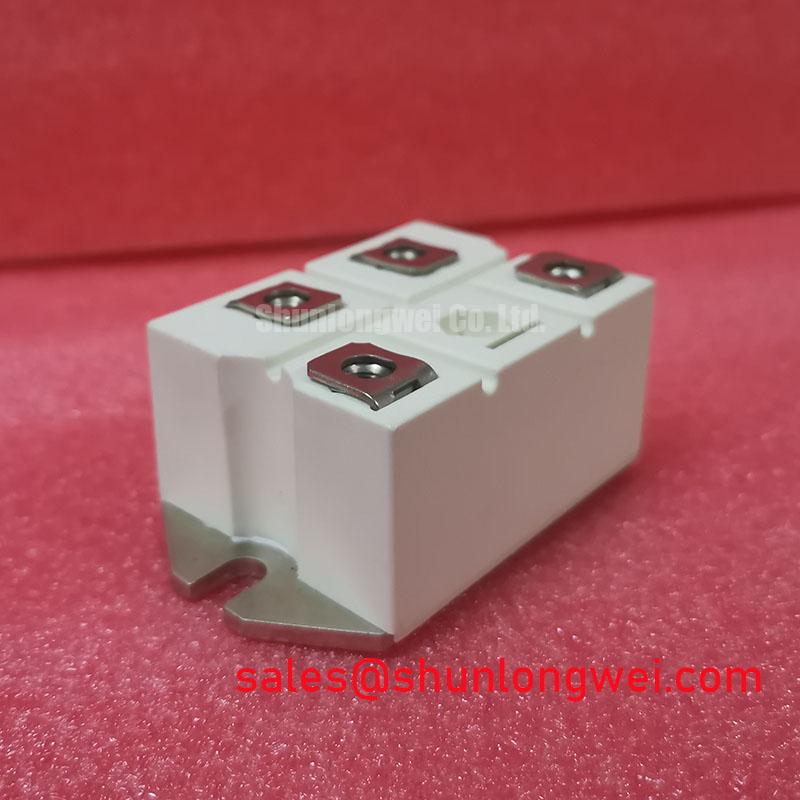
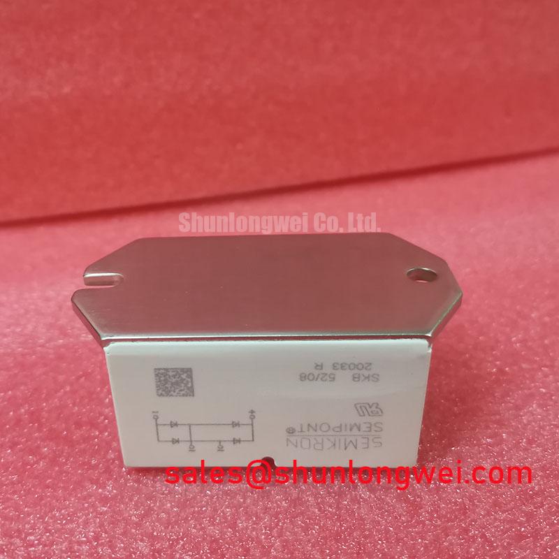
Check the terminal markings and cold-state conduction paths before fitting the SKB52-08 to an existing rectifier assembly. The supplied product specification identifies it as a Semikron bridge rectifier module with a 52.0 A rated current and a Semipont package. It does not establish a numerical voltage rating, surge-current limit, terminal torque or fuse coordination value; verify those boundaries against the applicable manufacturer datasheet before energizing the equipment.
A brief input fault can heat rectifier junctions well beyond what a steady-state current reading suggests. For a return-to-service assessment, record the fault duration, inspect the associated fuse and terminals, and compare the event with the manufacturer’s specified surge-current conditions. The 52.0 A rating is an Official Specification in the supplied product data, but it is not a substitute for a verified surge rating or a fuse coordination table.
As a Design Consideration, allow the rectifier to cool before returning it to service after a severe surge. Where the original documentation provides transient thermal impedance and surge data, use its stated initial-temperature and pulse conditions rather than treating a single surge figure as repeatable duty. Inspect the mounting surface and aged thermal interface during replacement, then confirm the specified fastening method and torque for the actual assembly. A Semipont housing should not be treated as a press-pack device requiring double-sided clamping.
For a different current or voltage requirement, SKD82/18 is a separate product to evaluate against the equipment drawing. Its terminal layout, mounting arrangement and electrical limits require independent confirmation; its model designation alone does not establish interchangeability with SKB52-08.
SKB52-08 Operational Boundaries at the AC Input
Trace the AC supply, bridge output and downstream DC link on the equipment schematic before attributing line-current distortion to the rectifier. In a medium-frequency induction melting or hardening furnace supply, the bridge may be evaluated as an input-rectification component, subject to the verified topology and ratings of that particular machine. Reactor impedance, DC-link loading and any downstream converter affect measured input current and power factor; the module’s 52.0 A rating alone cannot define line-filter limits.
Firing-angle analysis does not apply to SKB52-08 unless the equipment drawing identifies a separate controlled rectifier stage. A bridge rectifier module should not be assigned thyristor gate terminals or an adjustable firing angle without supporting device documentation. If an auxiliary rectification stage appears on the drawing, SKD 25/14 can be examined as a distinct component, not assumed to be part of this module.
For maintenance, compare input waveforms with the machine’s known-good records and check the line filter under its actual load. A change in waveform may reflect several system conditions, so confirm the source with measurements before specifying a filter or replacing the bridge.
SKB52-08 Circuit Protection and Maintenance Checks
Coordinate the input fuse, surge protection and any snubber network with the verified reverse-voltage and surge limits for the exact SKB52-08 revision. The supplied specification gives no numerical values for those limits, fuse I²t, mounting torque or terminal connection capacity. MOV and snubber selection therefore belongs to the system design and its measured supply environment, rather than to an assumed module rating.
As a Design Consideration, place protective devices according to the equipment schematic and verify that switching or supply transients remain within documented rectifier limits. Semikron-Danfoss’s official power-electronics hub is an appropriate manufacturer reference for locating the applicable product documentation. The MiniSKiiP power-module range describes a different product line and should not be used to infer Semipont mounting or electrical specifications.
Maintenance note: Isolate the supply before checking terminal tightness, heatsink cleanliness and signs of deterioration at the thermal interface. During scheduled inspections, trend terminal temperature under comparable load and check airflow and condensation exposure. These observations can guide investigation, but they do not establish a service-life figure for the module.
Preventing Misdiagnosis of SKB52-08 Rectifier Faults
A suspected bridge failure calls for measurements at the rectifier terminals, not adjustments to a gate-drive circuit. With power isolated and stored energy discharged under the site procedure, compare cold-state conduction paths with the documented terminal diagram and a known-good assembly where available. If readings differ, isolate connected circuitry before deciding whether the module or an external path accounts for the result.
Gate-pulse rise time, holding-current back-porch settings, Miller charge and negative off-bias are not verified SKB52-08 specifications. They concern controlled switches elsewhere in some power converters. The article Evolution of Negative Off-Bias Gate Drive Circuits may help when troubleshooting such a separate inverter stage, but it should not be applied as a gate-drive procedure for this bridge rectifier. For this module, finish the fault assessment by confirming the terminal diagram, the documented voltage and surge limits, fuse coordination, mounting instructions and measured operating conditions.