


Content last revised on October 2, 2026
SKD82-16 Operational Boundaries: Checking Half-Cycle Surge Duty
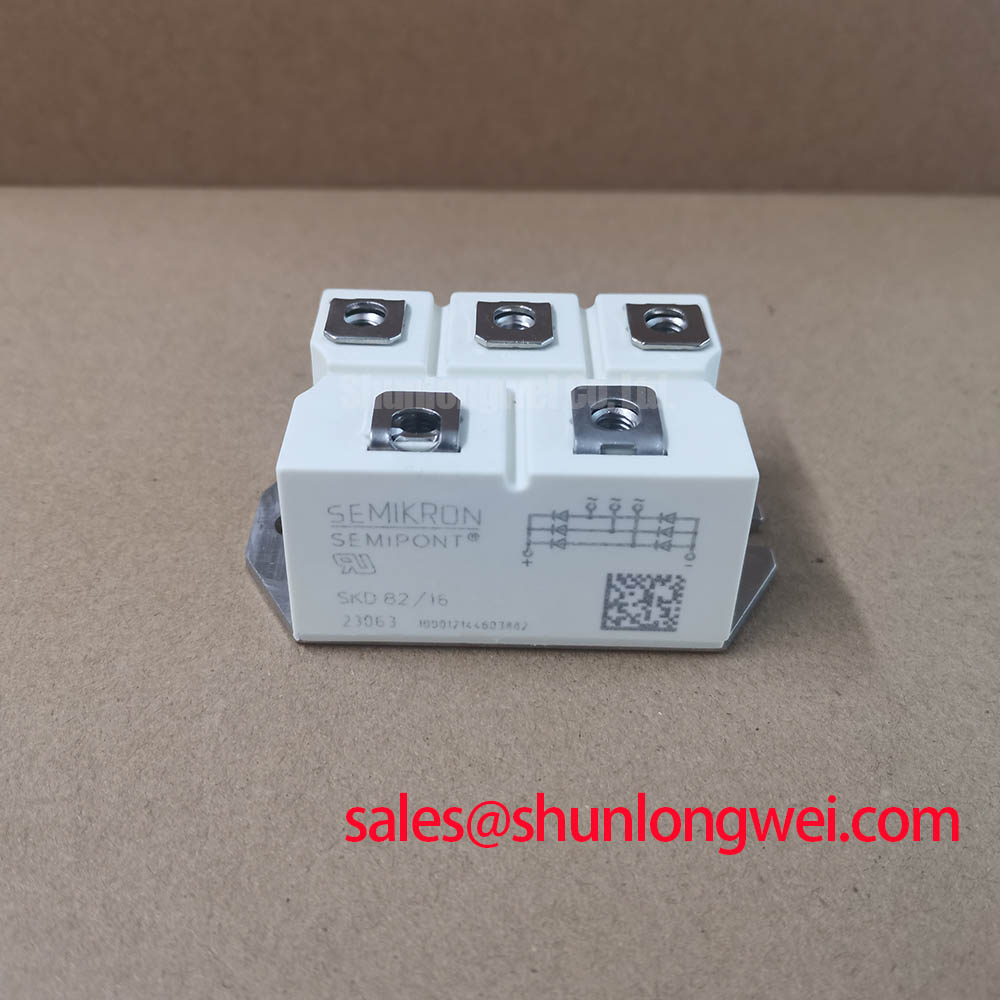
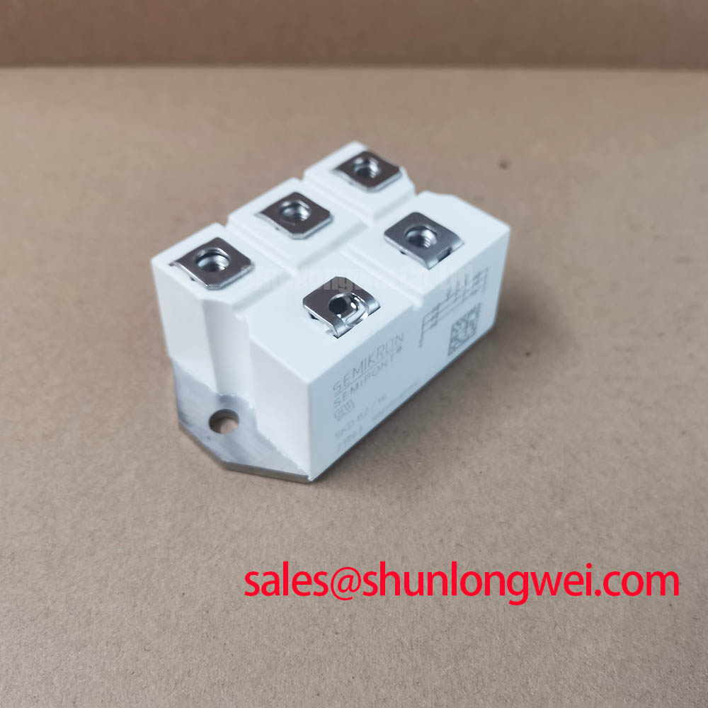
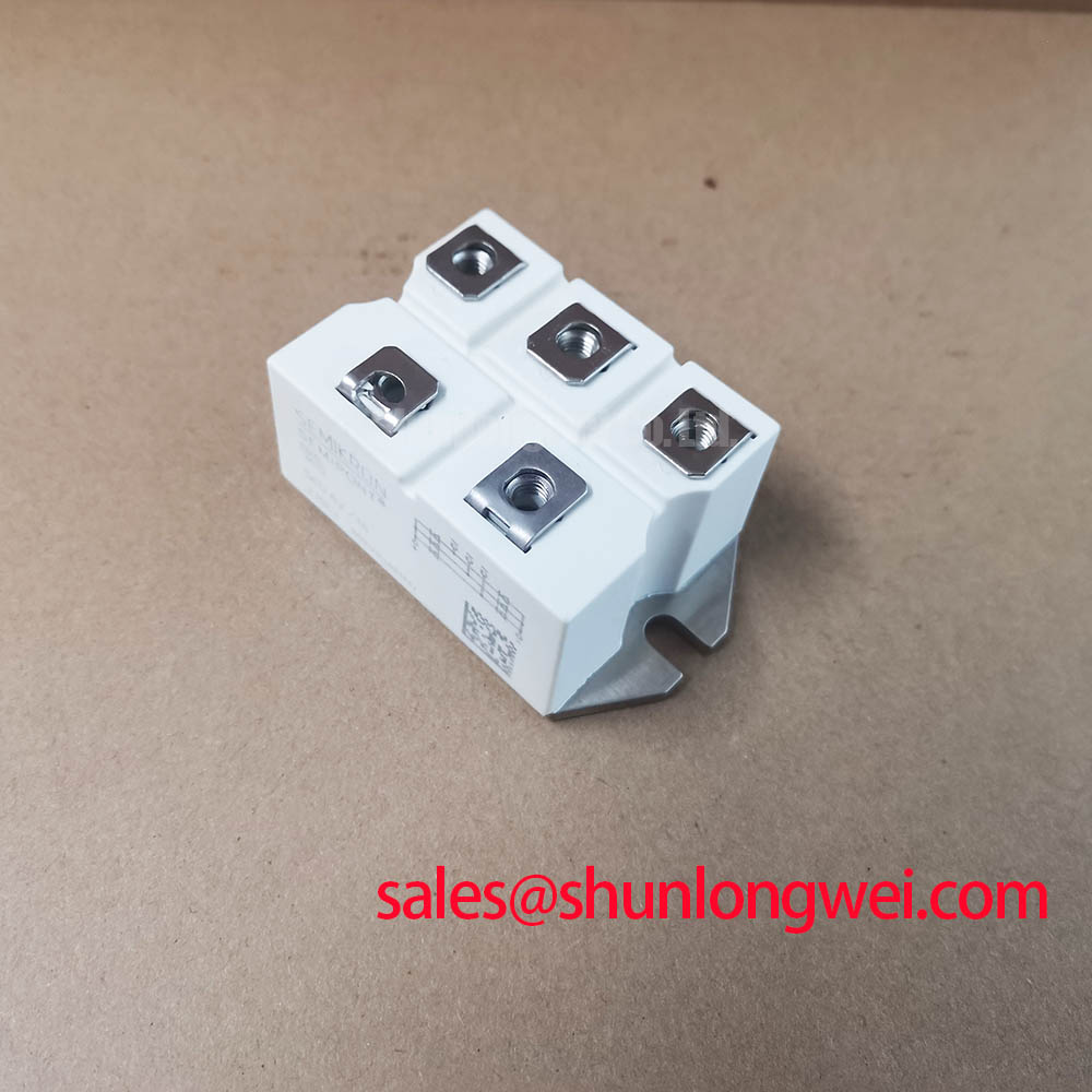
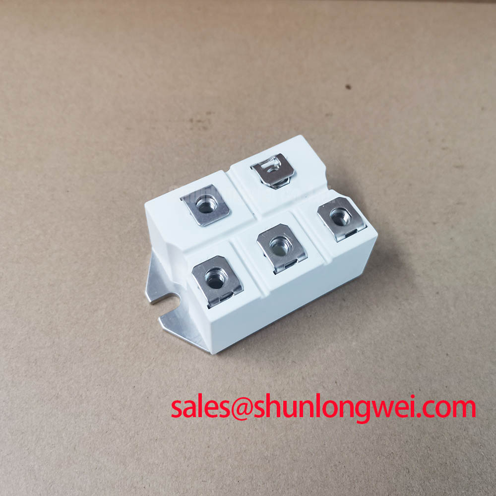
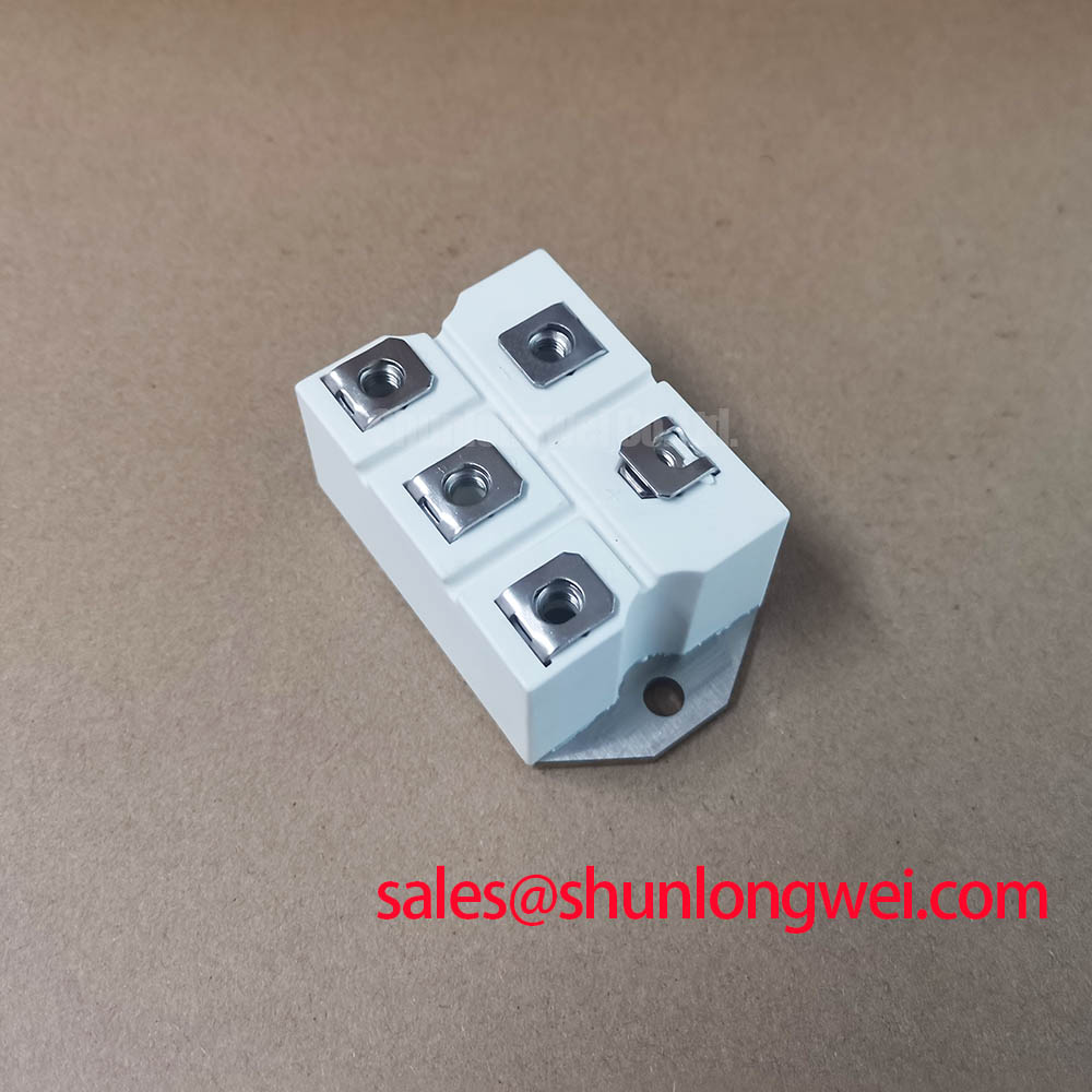
Isolate the AC supply and compare the terminal markings on the installed module with the circuit drawing before assessing a SKD82-16 replacement. The supplied product record identifies a Semikron Semipont bridge rectifier, but its voltage and current ratings should be confirmed against the exact part datasheet. This distinction matters when selecting a rectifier for a drive cabinet: a matching case does not establish matching electrical limits.
For a bridge rectifier, the relevant short-duration current limit is the surge rating of its diodes under the test conditions stated by the manufacturer. Before judging whether the SKD82-16 can withstand an input fault or charging transient, obtain the exact datasheet and check its half-cycle surge current, initial junction temperature and permitted repetition conditions. A surge figure quoted without those conditions cannot establish suitability for repeated motor starts or faults.
Compare the upstream fuse’s clearing characteristics with the rectifier’s specified surge and energy limits at the prospective fault current. The fuse and rectifier must be assessed as a coordinated circuit, not as two components with individually adequate nameplate currents. At the workbench, also compare the original module’s terminal layout, mounting footprint and heat-sink contact area. Use the manufacturer’s instructions for terminal and mounting torque rather than transferring a value from a visually similar Semipont case.
For a repair requiring a related part, SKD82/18 is a candidate for a documented comparison, not an automatic substitute. Verify its complete electrical ratings, terminal arrangement and mechanical fit against the original circuit requirements.
SKD82-16 Thermal and Electrical Integration: Input Surge Protection
Trace the power path from the AC terminals through the bridge to the DC load before selecting protective parts. A metal oxide varistor or RC network can be evaluated to limit transients reaching the rectifier, but its location and ratings depend on the measured supply waveform, source impedance and equipment insulation design. IEC 61000-4-5 describes a system-level surge test framework; it does not confer surge compliance on a standalone rectifier.
Rectifier heating depends on the actual current waveform and cooling path. Check the applicable manufacturer curves for the installed heat sink and ambient conditions, then inspect the mating surface and thermal interface during assembly. Field alert: Keep the equipment isolated while checking terminal connections and mounting hardware. If dielectric withstand is part of the equipment acceptance procedure, distinguish the completed assembly’s test requirements from any component rating; dielectric strength describes a material breakdown property, not proof that an assembled cabinet has passed an insulation test.
A three-phase motor soft starter is one possible equipment context, but its motor-current control path must be identified separately from any AC-to-DC auxiliary supply. A rectifier in that auxiliary path could be considered alongside other power-stage components such as SKD 25/14 only after the schematic establishes each device’s role.
Preventing Spurious Faults: Distinguishing Rectifier Behavior From Gate Triggering
Do not apply thyristor gate-trigger criteria to the SKD82-16 bridge rectifier. A diode bridge has no gate input to tune with firing-pulse rise time, holding-current pulses or a multi-pulse firing scheme. Those checks belong to the separately controlled thyristor stage of a soft starter, if that stage is present.
When an input fault appears intermittent, compare the AC input and DC output waveforms against the circuit drawing and a known-good operating condition. Check for loose terminals, unexpected voltage drop and changes in load current without assigning a single cause from one symptom. If a drive board uses optocouplers or digital isolators for another power stage, assess their transient immunity against that stage’s measured switching environment; it is not an SKD82-16 specification. Pro tip: Keep the rectifier fault trace separate from the thyristor gate trace so that a missing DC output is not mistaken for a firing-command problem.
For background on controlled semiconductor switching during a wider drive investigation, see The Ultimate IGBT Knowledge Base. Manufacturer documentation remains the reference for part-specific limits; the Semikron-Danfoss official hub is the appropriate starting point for identifying the applicable product literature.
SKD82-16 Operational Boundaries: Harmonics and Line-Filter Assessment
A diode bridge’s conversion behavior should not be described by a thyristor firing-angle range. The SKD82-16 has no adjustable firing angle; its AC input current waveform follows the connected DC load and the surrounding supply circuit. Consequently, line-filter and power-factor decisions require measurements or a system model of the complete equipment, not an assumed rectifier-only transfer characteristic.
During integration, record the AC line waveform and the DC-side loading under representative operating conditions. Compare the measured harmonics and temperature rise with the equipment’s design limits, then assess any proposed filter for its effect on input transients and upstream protection. For a soft-starter repair, confirm from the schematic whether this bridge feeds an auxiliary DC circuit before attributing motor-line harmonics to it. Release the replacement decision only after confirming its electrical ratings against the exact manufacturer datasheet.