Content last revised on October 16, 2026
2DI100A-140 Power Diode Bridge Module: Ratings and Installation Checks
- Confirm the nameplate rating: 1400.0 V voltage class and 100.0 A rated current.
- Inspect the power terminals, copper busbar interfaces, and insulating clearances before energization.
- Check that the heatsink surface is clean, flat, and free from dried thermal compound or foreign particles.
- Verify fuse coordination, terminal polarity, and rectifier control topology against the equipment documentation.
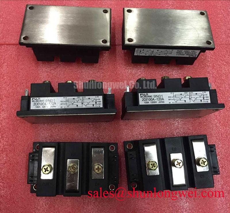
The Fuji Electric 2DI100A-140 is identified as a Power Diode Bridge Module with an official rated voltage of 1400.0 V and an official rated current of 100.0 A. These are the primary replacement-screening values for industrial rectifier assemblies, including high-current DC power sections used in electrolyzer systems. The available product data does not establish a gate terminal, gate trigger current, gate charge, or gate-driver requirement because this is a diode bridge module rather than a gate-controlled IGBT or thyristor device.
| Parameter | Specification | Engineering Use |
|---|---|---|
| Manufacturer | Fuji Electric | Cross-reference against the original equipment bill of materials |
| Model | 2DI100A-140 | Replacement identification |
| Rated voltage | 1400.0 V | Rectifier voltage-class screening |
| Rated current | 100.0 A | Rated-current class screening |
| Package | Power Diode Bridge Module | Mechanical and thermal integration review |
2DI100A-140 Operational Boundaries: Evaluating Phase-Controlled Rectification and Firing-Angle Limits
Phase-controlled rectification must be separated from the diode bridge itself: the firing angle is established by upstream thyristors, line controllers, or a converter topology, while the 2DI100A-140 conducts according to the applied line waveform and its rectifier polarity. When evaluating an AC-to-DC power rectifier, technicians should record the DC output trend as the controller advances the firing angle from a low-delay condition toward a high-delay condition. The resulting reduction in average DC output is accompanied by greater reactive demand and usually a less favorable input power factor at the system level.
That assessment belongs to the complete converter, not to the diode module as an isolated component. Confirm the line-to-line voltage, transformer arrangement, phase sequence, commutation behavior, and DC-link loading before interpreting current imbalance. For a high-current green hydrogen electrolyzer DC power rectifier, the inspection should also include busbar temperature, phase-current balance, and the effect of harmonic filtering on the upstream supply.
Fuse selection requires coordination between the fuse clearing characteristic, available fault current, and the bridge assembly’s permitted surge and I²t limits. Do not substitute a fuse solely because its continuous ampere label appears compatible. Use the applicable Fuji Electric fuse coordination data and compare it with the installed transformer and busbar fault environment. Terminal polarity and bridge connections should be checked against the equipment schematic before tightening conductors.
For a neutral comparison during procurement, engineers may review the higher-current 2DI300A-050, but its voltage, current class, mechanical arrangement, and thermal requirements must be evaluated independently rather than treated as a direct replacement.
Preventing Spurious Faults: Gate Trigger Current and Temperature Guidelines for 2DI100A-140
A gate-trigger analysis is not applicable to this diode bridge module because the published product category does not identify a gate-controlled semiconductor structure. References to gate pulse rise time, gate holding current, multi-pulse firing, Miller charge, or active gate clamping belong to an IGBT or thyristor design review. Applying those checks to the wrong component can divert troubleshooting away from the actual causes of abnormal rectifier behavior, such as phase loss, reverse-polarity connection, commutation stress, fuse mismatch, or thermal interface deterioration.
Temperature still matters at the assembly level. During commissioning, compare phase currents and monitor the temperature rise at equivalent terminal locations under a stable load. A localized temperature difference should prompt inspection of conductor seating, contact pressure, busbar alignment, airflow, and thermal compound coverage rather than an assumed semiconductor gate fault.
Fuji Electric’s power semiconductor technology resources provide useful manufacturer context for distinguishing diode modules from controlled switching devices. If the converter also contains IGBT switching stages, the adjacent drive and switching loop should be reviewed separately using the relevant Fuji Electric high-speed discrete IGBT information.
2DI100A-140 Circuit Protection and Reliability: Calibrating Thermal Interface Material Spreading
Thermal reliability depends on even contact between the module baseplate and heatsink, controlled fastener loading, and a continuous but restrained thermal interface layer. The official data supplied for this product identifies the package, voltage, and current ratings, but does not provide a thermal resistance value or an installation torque value here. Use the applicable Fuji Electric mechanical and thermal documentation for those figures rather than transferring a torque or Rth value from another package.
Before mounting, clean both contact surfaces with a suitable lint-free method and inspect for burrs, dents, or trapped particles. Apply thermal compound in a uniform thin layer appropriate to the interface material. Tighten the mounting hardware progressively so the module is not forced into distortion. After operation at a representative load, compare the temperature distribution across the heatsink and inspect for dry areas or excessive compound displacement during the next service interval.
Maintenance Note: De-energize and isolate the rectifier before retightening terminals, and periodically check heatsink cleanliness, airflow, and contact-temperature trends for signs of worsening thermal transfer.
For system-level switching sections connected to the same DC bus, minimize commutation-loop parasitic inductance to limit turn-off overshoot, then verify peak voltage against the equipment insulation and semiconductor limits during controlled testing. The practical integration principles collected in IGBT Design and Integration can support that adjacent switching-stage review, while the diode bridge remains assessed according to its rectification, protection, terminal, and thermal duties.