
Content last revised on September 11, 2026
Preventing Frame Lag & Image Smearing in Cryogenic Storage & Outdoor Industrial Facilities
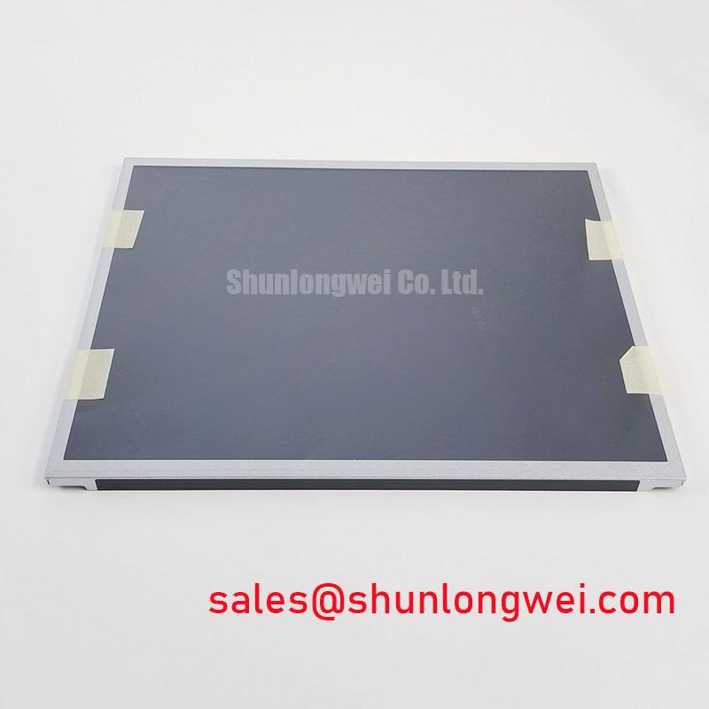
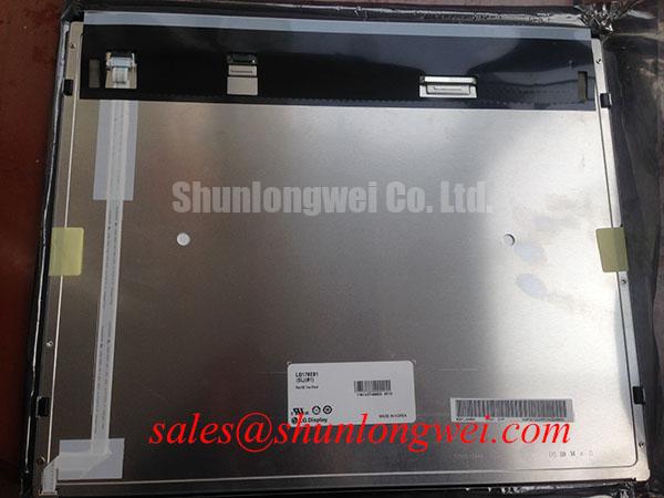
Begin incoming inspection by placing the LB170E01-SL01 on a clean ESD-safe bench, checking the TFT-LCD display module frame for twist, edge damage, connector contamination, and visible pressure marks before any power is applied. This LG Display unit is identified as an Industrial Grade LCD/HMI Panel in the official factory specification record. The available official information confirms the product category, manufacturer, module construction, and verified specification status; the system integrator should obtain the original panel documentation before assigning electrical, optical, interface, environmental, or mounting values.
| Item | Official Specification |
|---|---|
| Model | LB170E01-SL01 |
| Manufacturer | LG Display |
| Product Category | Industrial Grade LCD/HMI Panel |
| Construction | TFT-LCD Display Module |
| Specification Status | Official Factory Spec Verified |
Run a full-screen white, black, red, green, and blue image sequence, together with a suitable moving test pattern, at the intended installation temperature before judging the panel’s motion quality. A slow transition, uneven dark field, or visible image persistence can arise from several sources, including the panel operating environment, host timing, cable condition, or the source image itself. It should not be assigned to one failure mechanism without comparison against a known-good signal path.
Cold and outdoor equipment evaluations require special care because liquid-crystal response can change with temperature. The stated material does not provide an official operating-temperature range, Gray-to-Gray response value, contrast-ratio figure, sunlight readability level, thermal-cycle qualification, perimeter seal construction, or anti-glare coating specification for LB170E01-SL01. These points remain documentation checks rather than published attributes of this listing.
As a Design Consideration, engineers evaluating use near refrigerated storage or outdoor machinery should test the complete display assembly at its actual enclosure temperature, ambient illumination, and source refresh conditions. Assess black-level uniformity after stabilization, compare moving grayscale patterns with static patterns, and record whether the effect changes when the host controller, harness, or backlight supply is substituted. For wider planning on enclosure conditions, integration tradeoffs, and display lifecycle practices, see Industrial Display & HMI Solutions.
Potential use in high-precision surgical navigation or ultrasound diagnostic display equipment must be evaluated against the equipment maker’s image-quality, electrical-safety, cleaning, enclosure, and validation requirements. The panel listing alone does not establish medical-system suitability or certification.
Aluminum Heat Spreader Sizing & Thermal Interface Placement along Narrow Display Edges
Inspect the rear housing and narrow edges without assuming that any particular edge is an approved thermal contact surface. The official factory information supplied for this model identifies it as a TFT-LCD module but does not define a heat-spreader rail, approved thermal-interface material, LED backlight construction, luminance decay target, or allowable chassis heat path. A clamp, rail, pad, or adhesive selected for another panel should therefore not be transferred automatically to LB170E01-SL01.
As a Design Consideration, thermal spreaders can reduce localized enclosure heating when the surrounding mechanical design has been verified to avoid display stress. The useful approach is to measure case temperature across the completed assembly, observe the image while the equipment reaches steady state, and inspect for brightness nonuniformity or pressure-related visual changes. Heat-transfer choices must be determined by the host chassis, airflow, surrounding power electronics, and measured thermal results.
Interface integrity deserves the same discipline. The supplied information does not confirm whether this panel uses TTL, LVDS, or another display interface, and it does not publish clock-jitter or data-hold limits. The system integrator should verify the required supply voltage, signal standard, connector pinout, power sequencing, and timing limits from the original panel documentation. Where a differential interface is confirmed by that documentation, cable routing, return-path continuity, shielding, and pair consistency should be assessed on the completed equipment rather than assumed from generic display practice.
Noise from nearby power stages can complicate signal diagnosis. Current-return behavior and measurement methods should be reviewed at the system level; the TI current-sense amplifier resource is useful background when tracing supply and ground-current disturbances, but it does not define any electrical characteristic of this panel. Likewise, insulation material references such as polyimide film information describe general material context and must not be treated as evidence of this module’s internal construction.
Flashlight Dark-Shadow Optical Diagnostic to Isolate Logic vs. Backlight Failure Modes
Use a controlled bench sequence when a powered unit appears dark or incomplete. First, connect only a documented compatible host interface and display full red, green, blue, white, and black fields. Second, inspect the image from normal viewing position and at shallow angles for lines, localized dim areas, intermittent content, or color imbalance. Third, in a low-ambient-light condition, direct a flashlight across the screen at an oblique angle while the known test pattern is active. A faint image under angled illumination can guide further investigation of illumination and drive paths, while a missing or distorted image can justify checking the host signal path, connector seating, and panel condition.
These observations are diagnostic clues, not conclusive fault assignments. A dark screen can involve the source board, cabling, power rails, control sequencing, display module, or associated illumination circuitry. Likewise, a line defect may be intermittent and can change with handling or temperature. Avoid flexing the glass, frame, or connector area to provoke a response, since that action can create additional damage and invalidate the inspection result.
💡 Bench Tip: Disconnect power before mating or releasing the display cable, then keep the connector flat and fully aligned during engagement to avoid uneven contact loading.
For each test image, photograph the full active area and note the host controller, cable assembly, power state, and ambient condition. This record helps maintenance teams distinguish a repeatable panel symptom from a system-level signal or power anomaly. Do not infer a particular backlight technology, driver arrangement, or internal bonding structure from the appearance of the fault because those construction details are not confirmed in the available official specification.
Industrial Bezel Mechanical Envelope Tolerances & Mounting Screw Torque Optimization
Before fitting LB170E01-SL01 into a replacement bezel, compare the mechanical drawing for the original equipment with the panel documentation and inspect the bezel for burrs, warped supports, displaced gasket material, and uneven contact points. The currently available official factory information does not provide module dimensions, mounting-hole locations, bezel clearances, screw size, screw torque, permissible frame loading, or front-surface compression limits. Those values must be taken from the original panel drawing and the equipment mechanical design.
As a Design Consideration, use an evenly supported bezel and tighten approved fasteners in a cross-pattern sequence only after confirming the correct fastener specification. Uneven compression can alter the optical appearance of a TFT-LCD assembly and may create visual effects that are mistaken for electrical defects. After installation, repeat the black-field and white-field inspection with the bezel fully assembled, then compare it with the image before mechanical fastening.
Check cable strain relief after the final closure of the equipment housing. A harness that remains electrically connected during open-bench testing can shift when the rear cover is installed, changing connector engagement or placing force on the display interface. When integrating this LG Display module into industrial HMI equipment, surgical navigation consoles, or ultrasound diagnostic display terminals, verify all electrical and mechanical compatibility against the original system documentation before release to service.