

Content last revised on April 26, 2026
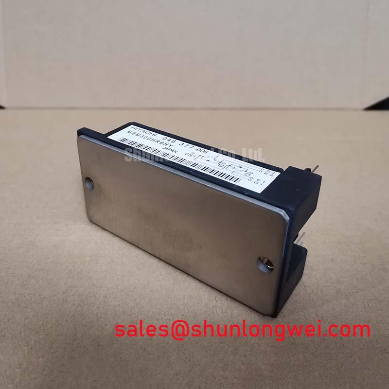
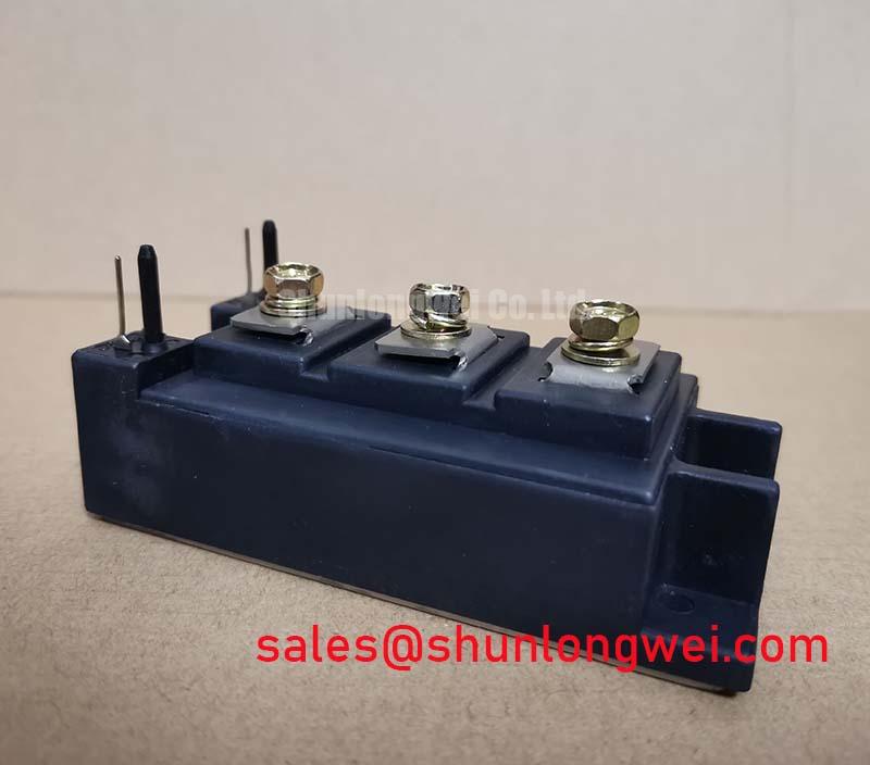
MBM300HR6HY | 600V 300A Single IGBT Module for High-Power Switching
Introduction to the MBM300HR6HY IGBT Module
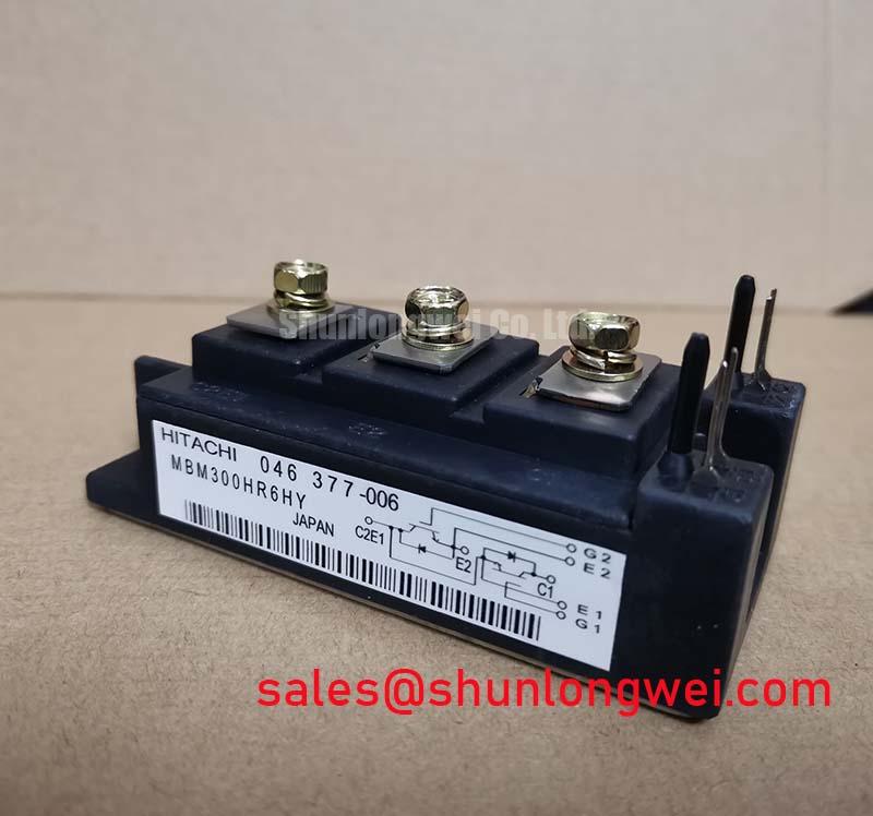
The MBM300HR6HY is a high-current 600V single IGBT module designed for robust power control where predictable thermal performance is key to system reliability. This component delivers a potent combination of high current handling and a flexible circuit topology. With core specifications of 600V | 300A | Vce(sat) 2.7V max, its primary engineering benefits are its substantial power handling capability and a versatile single-switch configuration. The module's significant collector-emitter saturation voltage necessitates a well-engineered thermal solution, including appropriate heatsinking and thermal interface material, to manage conduction losses effectively and ensure long-term operational integrity.
Application Scenarios & Value
System-Level Benefits in High-Current Industrial Converters
For high-current DC chopper and welding applications where thermal robustness is prioritized over switching frequency, the MBM300HR6HY provides a proven solution. Its design is particularly well-suited for legacy and new systems requiring precise control over substantial electrical loads. What is the primary impact of a 2.7V Vce(sat)? It dictates a focus on robust thermal management.
A prime engineering scenario is in the power stage of an industrial induction heating system. In such a DC Chopper circuit, the module must handle sustained high currents during the heating cycle. The MBM300HR6HY's 300A rating provides the necessary headroom, but its 2.7V Vce(sat) creates a significant and predictable thermal load. This allows engineers to precisely calculate and implement a robust thermal management system to keep the junction temperature well within its Safe Operating Area (SOA), ensuring high reliability during continuous operation. The simplicity of the single-switch design also allows for easy implementation of protective circuits, such as a snubber circuit, to manage switching transients.
While the MBM300HR6HY is optimized for 200-400V systems, applications requiring operation on higher voltage buses would utilize a device like the CM600DX-24T, which offers a 1200V rating.
Key Parameter Overview
Decoding the Specs for Robust Thermal Design
The technical specifications of the MBM300HR6HY highlight its role as a high-power switching device. The parameters are grouped below to facilitate evaluation for industrial power applications, with a focus on the values that directly influence thermal design and overall system ruggedness.
| Absolute Maximum Ratings (Tc = 25°C) | |
|---|---|
| Collector-Emitter Voltage (Vces) | 600 V |
| Gate-Emitter Voltage (Vges) | ±20 V |
| Continuous Collector Current (Ic) | 300 A |
| Pulsed Collector Current (Icp) | 600 A |
| Max Power Dissipation (Pc) | 1040 W |
| Electrical Characteristics (Tj = 25°C) | |
| Collector-Emitter Saturation Voltage (Vce(sat)) @ Ic=300A, Vge=15V | 2.7 V (Max) |
| Gate-Emitter Threshold Voltage (Vge(th)) | 4.0 to 8.0 V |
| Collector Cut-off Current (Ices) | 1.0 mA |
| Thermal and Switching Characteristics | |
| Operating Junction Temperature (Tj) | -40 to +150 °C |
| Storage Temperature (Tstg) | -40 to +125 °C |
Disclaimer: The parameters listed above are aggregated from publicly available data and are for reference purposes only. They are not guaranteed by the distributor.
Frequently Asked Questions (FAQ)
Engineering Considerations for Reliable Operation
How does the MBM300HR6HY's maximum Vce(sat) of 2.7V influence the thermal design of a power converter?
A Vce(sat) of 2.7V at a nominal current of 300A translates to a potential conduction loss of 810 watts (P = V*I). This substantial heat generation makes heatsink selection, thermal interface material (TIM) quality, and airflow design the most critical aspects of system integration. The design must be engineered to efficiently dissipate this heat to keep the IGBT's junction temperature below its 150°C maximum rating to ensure reliability and prevent premature failure.
What are the primary advantages of a single-switch 'chopper' configuration in an IGBT module?
The primary advantage is design flexibility. What topology does the MBM300HR6HY use? A flexible single-switch (chopper) configuration. This allows engineers to use the module as a standalone high-power switch in DC-DC converters (buck or boost), as a braking chopper in a Variable Frequency Drive (VFD), or to build custom inverter legs. This contrasts with more integrated modules (like six-packs) which are fixed into a three-phase bridge topology.
Given its parameters, is the MBM300HR6HY suitable for high-frequency applications like a modern SMPS?
This module is optimized for low-frequency, high-current applications rather than high-frequency switching. The datasheet characteristics, particularly the relatively high saturation voltage and associated switching times, suggest that switching losses would become excessive at higher frequencies (typically above 10-15 kHz). Its strengths are best leveraged in applications like motor control, welding, and induction heating, where switching frequencies are generally lower.
Technical Deep Dive
A Closer Look at Conduction Loss and its Impact on Thermal Reliability
The defining parameter for the MBM300HR6HY is its collector-emitter saturation voltage, Vce(sat). This value is the key determinant of conduction losses, which are often the dominant source of heat in high-current, low-frequency applications. The relationship is straightforward: Power Loss (P) ≈ Vce(sat) × Collector Current (Ic). For this module, at its maximum rated continuous current of 300A, the heat generated from conduction losses alone can be up to 810W.
Think of Vce(sat) as the pressure drop across a valve in a water pipe. Even when the valve is fully open (the IGBT is 'on'), there is still some inherent resistance, causing a loss in pressure. In the IGBT module, this "pressure loss" is the saturation voltage, and it manifests directly as heat. A higher Vce(sat) is like a less efficient valve, creating more friction and generating more heat for the same amount of water (current) flowing through it. Properly managing this thermal output is non-negotiable for achieving the component's specified operational lifetime.
Engineering Support and Component Sourcing
For systems requiring a robust, high-current switching solution, the MBM300HR6HY provides a foundation for reliable power design. Integrating this component successfully depends on a thorough understanding of its thermal characteristics and the implementation of an appropriate management strategy. To discuss the specific thermal and electrical requirements for your application, or to inquire about component evaluation, contact our technical support team for an in-depth analysis and sourcing assistance.