

Content last revised on October 15, 2026
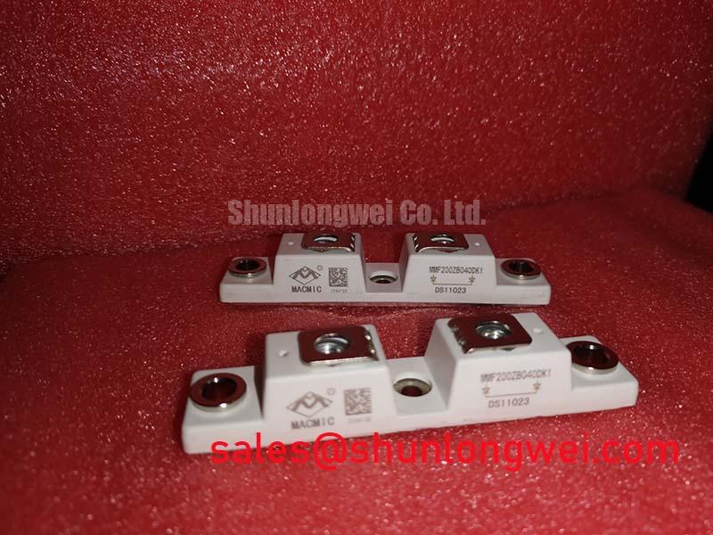
MMF200ZV040DK1 Operational Boundaries: Evaluating Junction-to-Case Thermal Network Simulation Limits
I check the case-temperature measurement location and recorded overload duration before interpreting a thermal event involving the MMF200ZV040DK1. A cool heatsink after shutdown does not establish the junction temperature during the preceding pulse. As a Design Consideration, capture the load waveform, switching conditions, and case-temperature history together so that the thermal assessment follows the actual operating event.
For an Engineering Calculation, use manufacturer-supported transient thermal impedance or a validated multi-RC model: junction-temperature rise follows the convolution of the device power-loss waveform with the thermal impulse response. Repeated overloads require the residual heat from preceding pulses to remain in the calculation. Compare the resulting peak junction temperature against the applicable device limit; arbitrary RC coefficients cannot establish a credible operating margin.
Inspect baseplate seating, heatsink flatness, and the thermal interface before changing protection settings. A junction-to-case model stops at the case boundary; interface and heatsink behavior need separate treatment. Field Alert: Follow the applicable mounting instructions for tightening sequence, torque, and thermal-interface application rather than borrowing values from a similar-looking module. The Power Electronics Masterclass provides broader engineering context for interpreting thermal stress and protection behavior.
Field Diagnostics & Commissioning: Preventing Terminal Overheating via Periodic Testing in MMF200ZV040DK1 Topologies
Measure each accessible bolted connection with a four-wire micro-ohmmeter after isolating the equipment and verifying discharge. As an Engineering Recommendation, place the sense probes across the joint itself, not across an uncontrolled length of busbar. Record connection temperature and probe positions so subsequent measurements remain comparable. Judge acceptance against the equipment manufacturer's connection specification rather than imposing a universal micro-ohm threshold.
During an authorized controlled-load test, compare thermographic profiles at equivalent joints under comparable current and cooling conditions. Surface emissivity and viewing angle can distort apparent temperature, particularly on reflective conductors. A localized hot area warrants examination of seating, contact surfaces, fastener condition, and current distribution; it does not identify a single cause by itself.
Protection coordination needs a separate check. As a Design Consideration, compare the semiconductor fuse's clearing characteristics and let-through energy with the protection requirements and withstand limits of the actual circuit. Fuse I²t alone does not establish IGBT short-circuit protection. Review fault detection, gate shutdown, and fault-current interruption together before restoring unrestricted operation.
Transient Dynamics & Electrical Design: DC-DC Converter Interleaving and Ripple Current on MMF200ZV040DK1
Compare phase-current waveforms and switching timing before attributing excessive DC-link ripple to the module. In an interleaved converter, ripple cancellation depends on phase relationships, inductance, and balanced loading. As a Design Consideration, assess operation across the intended duty range rather than checking cancellation at a single operating point.
For compatibility assessment in commercial string inverters and micro-grid energy-storage converters, trace charging and discharging paths separately. Bidirectional energy transfer does not by itself establish four-quadrant capability. Designers should verify the complete topology, reverse-current paths, and control transitions. If the equipment includes a braking chopper, check its resistor and protection coordination against the energy that the DC link must absorb.
Where a bootstrap gate supply is present, inspect its recharge opportunity, supply droop, and diode recovery during the longest commanded on-time. These are gate-driver integration checks, not established internal features of this module. Minimize commutation-loop inductance to limit switching overshoot, with conductor spacing and clearance determined by the equipment's voltage and insulation requirements.
When reviewing adjacent converter stages, the FF650R17IE4P can be considered separately in the complementary-stage assessment; it is not evidence of a compatible rectifier or replacement arrangement. ROHM's Field Stop Trench IGBTs and Intelligent Modules information offers general switching-device context without establishing MacMic-specific characteristics.
Field Diagnostics & Commissioning: Symmetrical Busbar Geometry for High-Current in MMF200ZV040DK1 Topologies
Compare parallel-branch current waveforms before relying on equal busbar dimensions as proof of balanced operation. As a Design Consideration, match power-path impedance, gate-loop routing, driver behavior, and cooling conditions. Static sharing and switching-edge sharing require separate observations because similar average currents can conceal unequal transient loading.
A positive temperature coefficient of on-state voltage can assist static sharing only where the device's characteristic curves establish that behavior at the operating point. Do not assume it across the entire current range. If temperature sensing is provided by the assembly, interpret the sensor through its documented thermal relationship to the switches; the general NTC thermistor operating principle does not establish an internal sensor in this model.
For replacement assessment, compare the CM200DY-12NFH against the original circuit drawing, terminal arrangement, mounting dimensions, blocking rating, gate requirements, and thermal characteristics. Treat it as a comparison candidate, not a verified direct replacement. Release the repaired assembly only after its connection checks, protection response, and controlled-load current-sharing measurements satisfy the equipment's acceptance criteria.