Shunlongwei Co. ltd.
IGBT Module / LCD Display Distributor
Customer Service
+86-755-8273 2562
IGBT Module / LCD Display Distributor
“Many Electronic circuits require a device to isolate or separate different circuits. This particular device is called a buffer, which is a unity-gain amplifier with very high input resistance and very low output resistance. This means that the buffer can be modeled as a voltage-controlled voltage source with a gain of 1. The buffer has almost infinite input resistance, so there is no loading effect, so VIN = VOUT.
“
Many electronic circuits require a device to isolate or separate different circuits. This particular device is called a buffer, which is a unity-gain amplifier with very high input resistance and very low output resistance. This means that the buffer can be modeled as a voltage-controlled voltage source with a gain of 1. The buffer has almost infinite input resistance, so there is no loading effect, so VIN = VOUT.
In addition, the output voltage of the buffer is insensitive to the load resistance because the output resistance of an ideal buffer is essentially zero. Placing a unity-gain buffer between the digital-to-analog converter (DAC) and the load can easily resolve the loading effect.
When adding unity-gain buffers to a system, it is important not to compromise accuracy and performance. The most important point is to calculate the added noise:
![]()
in:
en = buffer input voltage noise density
in = buffer input current noise density
f = device input bandwidth (Hz)
In the circuit shown in Figure 1, the current noise per channel is very low (0.8 fA/√Hz); in comparison, the voltage noise is (13 nV/√Hz). Therefore, to reduce the added noise in the system, this voltage noise must be reduced. Placing multiple buffers in parallel reduces voltage noise. For example, paralleling two buffers reduces the voltage noise by √22, and paralleling all four buffers is equivalent to a buffer with half the noise. The disadvantages of this approach are increased bias current, current noise, and input capacitance, but these effects are negligible in this example. Placing a small resistor like 50 Ω between the outputs prevents extra current flow due to small differences between the outputs. For less power-sensitive applications, these 50 Ω resistors can be omitted to increase the available output current.
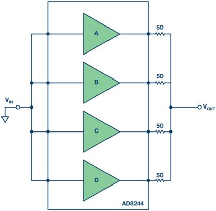
Figure 1. AD8244 New Low Noise Buffer
The circuit shown in Figure 1 is a novel configuration of a buffer amplifier that cuts the voltage noise in half. The AD8244 is a quad, JFET-input, unity-gain buffer that delivers much higher performance than expected. With a maximum bias current of 2 pA, near-zero current noise, and an input impedance of 10 TΩ, there is virtually no error even with MΩ-level source impedance. The device features low voltage noise, wide supply range, high accuracy, and is flexible enough to provide high performance for any application requiring unity gain buffers (even low source resistance).
Figure 2 compares the noise performance of a common single-channel buffer and the new AD8244 buffer with four parallel channels.

Figure 2. AD8244 Buffer Performance: Half the Noise of a Normal Buffer