

Content last revised on September 29, 2026
VSKT250/16PBF RC Snubber and Gate Circuit Checks
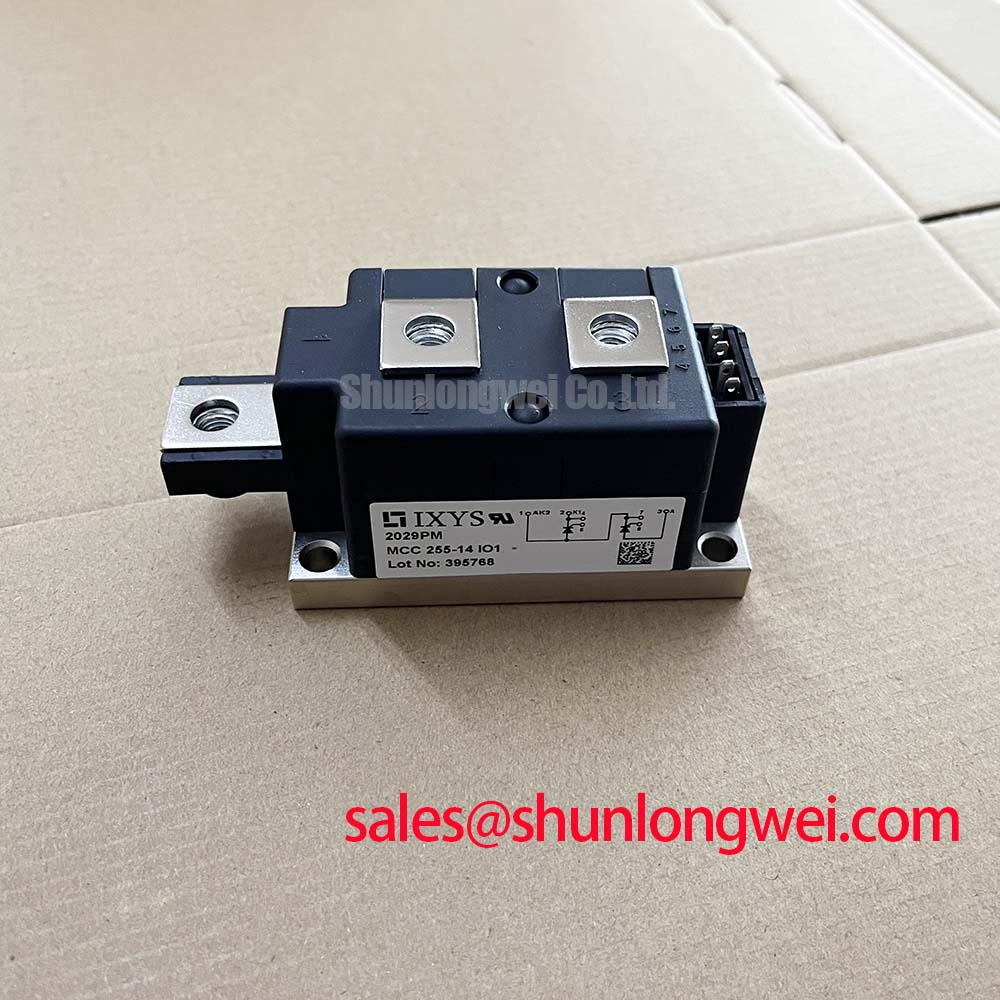
Check the terminal identification against the equipment wiring diagram and verify the module marking before connecting VSKT250/16PBF to a firing circuit. Vishay specifies a 1600 V repetitive peak reverse voltage and a 250 A average on-state current at a case temperature of 85 °C (Official Specifications). Those ratings establish a starting point for assessment, not a substitute for checking the installed circuit, cooling path and protection scheme.
In a thyristor circuit, a rapid rise in off-state voltage can contribute to unintended turn-on if the surrounding circuit does not adequately control transients. An RC snubber is a system-level Design Consideration: select its resistor and capacitor from measured voltage waveforms, expected switching conditions and the applicable thyristor datasheet limits. Verify the result at the module terminals rather than assuming that a snubber retained from another assembly provides the same protection.
Inspect the gate wiring route, return connection and firing waveform when investigating intermittent starts. Parasitic inductance and coupled noise can distort a gate pulse; pulse-train firing should be assessed against the original controller design and the module’s specified gate-trigger requirements. If a series saturable reactor is present, confirm its connections and condition before changing it. A reactor or snubber change must also be checked for its effect on commutation and voltage stress.
Vishay rates the module’s RMS on-state current at 555 A (Official Specification). That figure does not define an allowable terminal temperature or a tightening torque. Confirm terminal connections and mounting instructions from the applicable Vishay documentation, then inspect the assembled joint for signs of heating. Maintenance Note: Isolate the equipment before retightening terminals, and check contact temperature trends and heatsink airflow after return to service.
Phase-Controlled Rectification and Protection Coordination
For phase-controlled rectification, delaying the firing angle reduces the portion of each AC cycle delivered to the load. The resulting DC output and input power factor depend on circuit topology, load current continuity and source impedance; they cannot be determined from this module’s current rating alone. Compare controller firing records with line and load waveforms when a repair is followed by poor regulation or unexpected reactive-power demand.
The 1600 V reverse-voltage rating (Official Specification) should be checked against repetitive blocking conditions and measured transients. In a complete power path, a separate module such as SKKT91/08D may appear in a related conversion stage; its topology, ratings and connections require an independent assessment. Likewise, VS-ST730C18L0 is a cross-model comparison point, not an assumed drop-in replacement. Compare the circuit configuration, gate-drive needs, mounting interface and cooling arrangement before considering any substitution.
Fuse coordination needs the prospective fault-current profile, the fuse manufacturer’s clearing and pre-arcing I²t data, and the module’s applicable surge and I²t limits. No fuse size or clearing result follows from the average-current rating alone. Inspect the protection schedule for the installed equipment rather than treating a steady-state current match as short-circuit protection.
Surge Current and Thermal Recovery
Vishay specifies a 9500 A non-repetitive on-state surge current at 50 Hz (Official Specification). It describes a defined surge condition, not a repeatedly available starting current. Review the datasheet’s test conditions and surge curves when assessing an event; the current waveform, initial junction temperature and subsequent voltage reapplication all matter. Do not infer a safe recovery interval from the headline surge figure.
The specified operating junction-temperature range is −40 °C to 125 °C, while the on-state voltage is 1.75 V at 1000 A and a junction temperature of 25 °C (Official Specifications). The voltage figure is tied to that test point and should not be used as a fixed loss value across a duty cycle. For maintenance, inspect heatsink fouling, fan performance, thermal-interface condition and terminal contact heating before attributing an overtemperature indication to the semiconductor.
Insulation spacing and moisture control are enclosure-level Design Considerations. Check clearances, creepage paths and evidence of condensation against the equipment documentation; the voltage rating alone does not establish installation-level insulation reliability. The Ultimate IGBT Knowledge Base provides broader power-semiconductor context, but IGBT switching guidance must not be substituted for thyristor firing or commutation limits. Vishay’s industrial power MOSFET information likewise concerns a different device family.
Phase-Angle Voltage Profiling in Motor Soft Starters
A high-voltage three-phase motor solid-state soft starter is one possible compatibility assessment for VSKT250/16PBF, subject to the actual module circuit, voltage waveform, start duration and cooling design. During a controlled start, the firing schedule changes the voltage applied to the motor. Record line current, terminal voltage and acceleration under the intended load; the module rating alone cannot establish a particular inrush-current reduction or guarantee freedom from torque disturbance.
Keep the high-current path and its connections under review when investigating voltage spikes or uneven phase behavior. Busbar layout and connection geometry can increase parasitic inductance, so any layout change should be verified by measuring peak voltage at the module during switching and comparing it with the specified blocking limits. Confirm that the controller delivers consistent gate pulses across the operating range, then check phase balance and heatsink temperature during the commissioned start sequence.