
Shunlongwei Co. ltd.
IGBT Module / LCD Display Distributor
Customer Service
+86-755-8273 2562
IGBT Module / LCD Display Distributor
“Before electricity was used, people used candles for lighting. This used to be a common way to see in the dark, but the invention of the light bulb was clearly a better solution.
“
Before electricity was used, people used candles for lighting. This used to be a common way to see in the dark, but the invention of the light bulb was clearly a better solution.
Like a candle, a power MOSFET (power field effect transistor) is the most common way to switch a load, surrounded by a number of discrete resistors and capacitors (and a bipolar junction transistor (BJT)/second field effect transistor) around the power MOSFET). In most cases, however, there are more significant advantages to using a fully integrated load switch.
Where is the load switch in the system
A typical system includes a power supply and multiple loads that require various load currents, such as Bluetooth®, Wi-Fi, or processor rails. In most cases, the system must independently control which loads are turned on, when, and at what speed. This power switching can be accomplished using discrete MOSFET circuits or an integrated load switch, as shown in Figure 1.
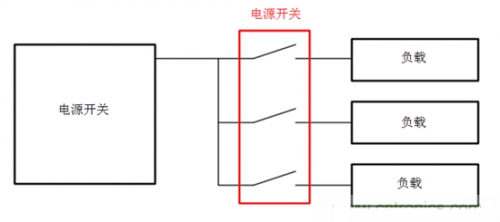
Figure 1: Switching from a power supply to multiple loads
Discrete MOSFET circuits contain multiple components to control the turn-on and turn-off of discrete power MOSFETs. These circuits can be turned on or off by general-purpose input/output (GPIO) signals from the microcontroller. Such a circuit can be seen in Figure 2.

Figure 2: P-channel MOSFET (PMOS) discrete circuit
Load switches can also be used to open or close the connection between the power rail and the corresponding load. These integrated devices have some benefits over their discrete counterparts. Figure 3 shows the load switch circuit.

Figure 3: Typical Load Switch Circuit
Size advantage
One advantage of using a load switch as a solution is the reduction in component count and size. The design of the load switch integrates components into a package that is even smaller than the MOSFET itself. Figure 4 compares the size of the PMOS scheme and an equivalent load switch. The smaller size of the load switch makes it ideal for even the most space-constrained applications.
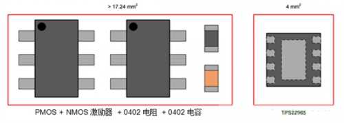
Figure 4: Size comparison of TPS22965 and equivalent discrete solutions
Features and advantages
The load switch also integrates some features not found in discrete circuits. Adding reverse current blocking to a discrete solution requires an additional MOSFET in a back-to-back configuration, which directly doubles the size. The TPS22910A and TPS22963C are examples of two load switch combinations from Texas Instruments that have this functionality built in.
Quick Output Discharge (QOD), a standard feature of Texas Instruments load switches, discharges the output voltage (VOUT) through an internal path to ground when the switch is off. Figure 5 is a schematic diagram of this function.
Figure 5: QOD description
QOD provides a known state on the output side and ensures that all loads are released and turned off.
The TPS22953 and TPS22954 feature a “power good” signal that occurs when the VOUT load reaches 90% of its final value. This signal flows into the downstream module enable pins, enabling these modules to turn on when the rails are powered up. The functionality of the “power good” signal can also be used for power sequencing, turning on a load switch will cause multiple power rails to appear in a specific order.
It is no exaggeration to say that the invention of the light bulb made it easier for people to see in the dark, and the challenge of integrating a load switch to design a compact and low-power circuit is as significant as the invention of the light bulb. Well, it’s time to blow out the candles and light up your power switching design with an integrated load switch.


