Content last revised on October 2, 2026
2MBI300P-140 Operational Boundaries: Evaluating PCB Symmetry Considerations for Dual IGBT Limits
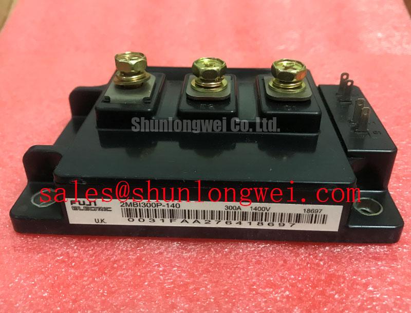
Check the 2MBI300P-140 terminal markings against the original circuit diagram before taking cold-state diode-mode readings across either half-bridge position. Record probe polarity and readings for both positions under the same conditions; a difference is a reason to investigate, not a diagnosis by itself. Fuji Electric lists this dual IGBT module in the M239 package with a 1400 V collector-emitter voltage rating and a 300 A continuous collector-current rating at 25°C case temperature (Official Specifications). Its collector-emitter saturation voltage is 2.8 V typical at 300 A (Official Specification); the original datasheet test conditions are needed before comparing that figure with a powered measurement.
The two switch positions form a half-bridge, but their connections on a drive board need separate scrutiny. During incoming inspection, identify each gate and emitter connection from the approved pin diagram, then compare gate-to-emitter resistance readings with the gate-driver circuitry disconnected. This cold-state check can reveal a wiring discrepancy without treating a multimeter reading as a dynamic switching specification.
Design Consideration: Keep each gate-driver return path distinct from the corresponding high-current emitter path wherever the documented terminal arrangement permits it. A voltage developed across a shared emitter path can disturb the voltage seen by the driver and contribute to unwanted switching behavior. Do not assume that the 2MBI300P-140 provides a dedicated Kelvin emitter terminal; confirm the available terminals in the original package drawing before laying out or reconnecting the driver board. Route the two gate paths consistently, and assess conductor spacing against the equipment’s working voltage, insulation scheme, environment, and applicable system standard. The module’s 1400 V rating does not, on its own, establish a board clearance or creepage requirement.
Bench Tip: Discharge the DC link and verify absence of voltage before moving probes between power terminals and gate connections. If one position shows unexpected gate activity after installation, compare its gate-to-emitter waveform with the other position using an appropriately isolated measurement setup. Inspect return-path routing and connector contact before attributing the symptom to the module.
2MBI300P-140 Operational Boundaries: Evaluating High-Frequency Commutation Loop Inductance Limits
Trace the commutation path from the DC-link capacitor through the active switch and its return path before deciding where a snubber belongs. During turn-off, loop inductance and the rate of current change add voltage to the DC-link level at the switching device. Design Consideration: Keep that loop compact and assess snubber placement and value through switching measurements, with the measured collector-emitter peak checked against the 1400 V Official Specification under the equipment’s relevant operating conditions. No loop-inductance target or snubber capacitance follows from the supplied module ratings alone.
For a laminated or planar bus structure, compare the physical paths feeding the upper and lower switch positions, including capacitor connections and fasteners. An apparently symmetrical drawing may still produce different waveforms if the actual current paths differ. Observe both turn-off peaks and diode commutation on the installed assembly before changing gate-drive or snubber components. Reverse-recovery behavior can affect switching noise and conducted or radiated emissions, but a diode softness factor or equipment EMC result cannot be inferred from the listed ratings. Fuji Electric’s RC-IGBT module information describes a different product family; it should not be used to assign its diode characteristics to this module.
Design Consideration: Verify complementary gate interlock and dead time from the drive-board timing diagram and measured gate waveforms. The interval must prevent simultaneous conduction while accounting for the actual driver delays and switching behavior; the system designer determines and validates it. In a heavy-duty variable-frequency AC motor drive, this check belongs alongside inspection of the DC-link and protection circuitry, not as a conclusion drawn from the module name. When reviewing adjacent positions in that equipment, 2MBI150UC-120 is a separate device to evaluate against its own ratings and circuit role, not an assumed rectifier or companion specified for the 2MBI300P-140.
Preventing Spurious Faults: Multi-Module Parallel Current Sharing Guidelines for 2MBI300P-140
Parallel operation requires evidence from the complete assembly. The stated 2.8 V typical Vce(sat) at 300 A is an Official Specification at a stated current, not proof that paralleled units will divide current evenly. Compare the original datasheet curves and test conditions before drawing conclusions about temperature-dependent sharing. In particular, do not assume a favorable positive temperature coefficient across the equipment’s full operating range from one typical saturation-voltage point.
Design Consideration: Compare bus-path lengths, connection resistance, cooling contact, gate-drive paths, and current-sensing placement for each parallel position. Static readings can identify gross differences in connections; dynamic current sharing needs measurements during representative switching. If a protection channel trips intermittently, inspect its sensor and driver waveform alongside the affected current path. A trip may reflect sensing noise, unequal switching, or another system condition, so the fault record should be checked before altering protection settings.
For a proposed cross-reference, 2MBI300U4H-120-50 can be placed on the engineering comparison sheet, but the shared current figure in the model name does not establish interchangeability. Verify voltage rating, package drawing, terminals, gate-drive requirements, losses, and thermal fit against the installed design. Cooling-path questions also benefit from the broader context in The Advanced Thermal Management Revolution; that discussion does not establish a lifetime or cooling specification for this particular module.
Preventing Spurious Faults: Fault-Clearing Dynamics: Type-I/II Desatur Guidelines for 2MBI300P-140
Start with the drive board’s fault schematic: identify where desaturation is sensed, how blanking is implemented, and what turns off the opposite switch after a fault. Distinguish a fault present at turn-on from one that develops during conduction when reviewing captured waveforms. Both cases require assessment of detection delay, gate behavior, and the voltage reached during current interruption. The supplied specifications do not state a short-circuit withstand time or short-circuit safe-operating-area limit for the 2MBI300P-140; neither a fixed clearing deadline nor a two-stage turn-off setting should be assigned to it without the relevant manufacturer data and system validation.
Design Consideration: A controlled fault turn-off may reduce inductive overshoot, but its timing and voltage trajectory must be checked on the installed bus and load. Record gate-to-emitter voltage, collector-emitter voltage, fault output, and DC-link voltage during an appropriately controlled test. If the gate rises while its switch is commanded off, examine coupling through reverse-transfer capacitance and the driver’s off-state behavior before selecting an active-clamp approach. The required clamp behavior and the isolator’s common-mode transient immunity are system-design questions, not specifications supplied for this module.
Finally, confirm that the equipment’s insulation assessment covers the installed terminal geometry and operating environment. At altitude, insulation coordination and power-device stress may require separate review; the listed ratings provide no altitude derating, cosmic-ray failure rate, or single-event-burnout margin. Keep those assessments tied to the applicable system requirements and supporting manufacturer data rather than treating them as module-level guarantees.