
Content last revised on September 16, 2026
PM75CSD120 Verification and Official Specifications
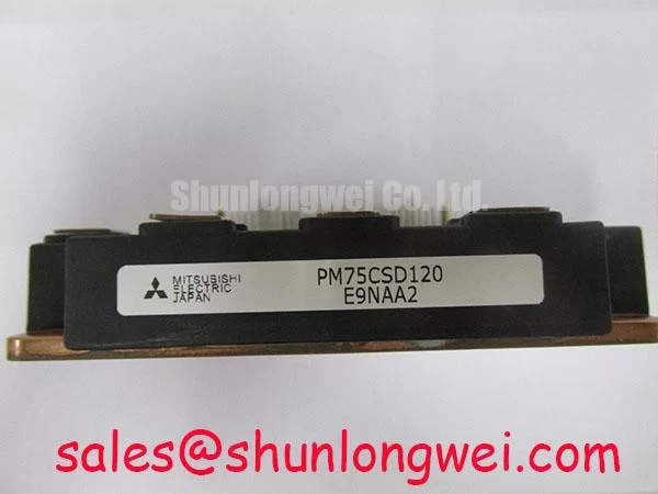
With the drive isolated and the DC link confirmed discharged, first verify that the installed power stage nameplate matches PM75CSD120 and that the replacement position is intended for a 1200 V, 75 A at Tc = 25°C Mitsubishi Electric power device.
| Official Specification | Value | Integration Relevance |
|---|---|---|
| Collector Emitter Voltage, VCES | 1200 V | Official Datasheet Specification for voltage blocking capability. |
| Collector Current, IC | 75 A at Tc = 25°C | Official Datasheet Specification for collector current under the stated case temperature condition. |
| Collector Emitter Saturation Voltage, VCE(sat) | 2.5 V typical | Official Datasheet Specification relevant to conduction loss assessment during the on state. |
| Isolation Voltage, VISO | 2500 Vrms | Official Datasheet Specification for the isolation boundary. |
| Junction Temperature, Tj | −20°C to +150°C | Official Datasheet Specification defining the stated junction temperature range. |
Benchtop Waveform Tuning: Mitigating Stress via DC Bus Operating Voltage Headroom Derating on PM75CSD120
The 1200 V VCES rating is the fixed device boundary, not a measured operating target. For a heavy duty variable frequency AC motor drive, commissioning should begin with a controlled DC bus condition and measured collector emitter waveforms at the actual switching nodes. The system engineer should compare peak voltage, ringing duration, current, and switching sequence against the available device margin while the motor, cable, busbar arrangement, and load condition are representative of service.
DC bus operating voltage headroom is a Design Consideration. Inductive overshoot is influenced by the switching current transition and the parasitic inductance of the commutation path. A compact current loop, direct local DC link support, and short gate return routing help suppress turn off overvoltage, but the acceptable result must be established by switching tests in the completed drive. A waveform that appears acceptable at reduced load can change materially when motor current, cable conditions, or regenerative operation change.
Sites above 2000 m require separate system level assessment. Terrestrial neutron exposure, ambient pressure, cooling capability, insulation coordination, enclosure contamination, and local installation rules are all conditions that can affect a high voltage converter design. No field failure rate, FIT value, or single event burnout rate should be inferred from the PM75CSD120 voltage rating alone. Designers should obtain the applicable equipment requirements and use measured voltage stress to determine the appropriate DC bus operating range.
For devices under comparison, the electrical topology, terminal arrangement, driver interface, thermal path, and protection behavior should be verified before a change is considered. The SKIIP37AC12T4V1 can be reviewed as a separate power semiconductor option, but its suitability is system determined and cannot be established from voltage class alone.
Field Diagnostics & Commissioning: High Speed Fault Management: VCE Desaturation in PM75CSD120 Topologies
In a drive topology using collector emitter desaturation monitoring, inspect the driver protection sequence before energizing a replacement PM75CSD120 position. Desaturation monitoring belongs to the gate driver and system protection architecture; it must not be represented as an internal protection specification of this device. The protection threshold, blanking interval, response time, and shutdown profile should be verified against the original drive documentation and measured on a controlled test setup.
A short circuit event can create a rapid rise in collector current while the IGBT is commanded on. A driver that identifies abnormal collector emitter behavior should transition the affected gate safely, while the system interlock prevents continued switching. Soft turn off is a Design Consideration where the protection architecture needs to limit the rate of current interruption and associated inductive voltage excursion. Its settings must be established from the actual commutation loop, load current, DC link condition, and measured transient behavior.
Keep the gate loop and power commutation path physically disciplined to reduce parasitic inductance. Gate emitter return routing should remain paired with its corresponding gate conductor, and DC link film capacitors should be placed according to the converter layout so transient current does not travel through a long shared path. Oscilloscope measurements should use an appropriate high voltage differential probe and a probing method that does not introduce misleading loop pickup.
When a power stage has repeated fault trips, inspect the driver supply stability, gate command symmetry, current sensing path, interlock logic, and DC link condition before attributing the issue to one device. A companion stage such as the CM100DY-12E may appear in related rectifier or converter arrangements, yet its role and interface must be confirmed from the equipment schematic.
The Mitsubishi DIPIPM™ Bootstrap Circuit Design note is useful background for reviewing bootstrap supply behavior in applicable driver circuits. It does not replace the PM75CSD120 system schematic or its original driver requirements.
PM75CSD120 Circuit Protection & Reliability: Baseplate Contact and Mounting Screw Checks
Thermal reliability starts with the mechanical interface. Before mounting, clean the heatsink contact surface, inspect it for flatness damage or embedded debris, and examine the device contact area for residue that could prevent uniform thermal transfer. The −20°C to +150°C junction temperature range is an Official Datasheet Specification, but it does not remove the need to validate case temperature, heatsink performance, airflow condition, and cycling duty in the finished equipment.
Thermal interface material should be applied as a controlled, uniform layer consistent with the material supplier instructions and the original equipment assembly method. Excess material can reduce mounting consistency, while insufficient coverage can leave localized thermal resistance. Where baseplate curvature is present, the mounting sequence should progressively distribute clamp load rather than pulling one side down first. The correct screw torque, hardware stack, and any spring washer arrangement must be taken from the original mechanical drawing or equipment service procedure.
Maintenance Note: Monitor contact temperature rise during scheduled service and verify that cooling passages remain clear before returning the drive to sustained load.
Semiconductor fusing and upstream protection should be reviewed as a coordinated system rather than selected from the 75 A collector current rating alone. The protective device must be evaluated against the converter fault path, available source energy, DC link capacitance, cable impedance, and the relevant short circuit behavior of the entire assembly. For a persistent hard fault, isolate the source, inspect the power path and gate driver, and confirm that the cause has been removed before installing a replacement device.
The specified 2500 Vrms isolation voltage identifies the official isolation rating, while system insulation reliability also depends on creepage, clearance, contamination level, enclosure moisture control, and service conditions. Industrial display documentation, including information available from NEC Display Solutions, should be treated separately from the power stage because display interface requirements do not establish converter isolation performance.
Field Diagnostics & Commissioning: Thermal Feedback in PM75CSD120 Topologies
The 2.5 V typical VCE(sat) value is an Official Datasheet Specification and is relevant to estimating conduction behavior, but it is not a fixed diagnostic threshold for a live inverter. Collector emitter voltage is affected by current, junction temperature, gate drive conditions, measurement technique, and switching state. Compare equivalent phase positions under matched operating conditions, then investigate meaningful deviation using a known good signal path and the equipment schematic.
In parallel or shared current arrangements, the temperature relationship of IGBT conduction characteristics can contribute to steady state current sharing, but dynamic current balance depends heavily on matched gate loop geometry, common driver reference behavior, switching timing, and power path symmetry. Designers should verify these conditions with synchronized voltage and current measurements rather than relying on static readings alone.
Long motor cables introduce transmission line effects that can produce reflected voltage at the motor end. Cable type, routing, motor insulation, output reactor selection, filter arrangement, and switching behavior determine the result. When integrating the PM75CSD120 in a heavy duty variable frequency AC motor drive, the system engineer should measure both inverter output and motor terminal waveforms under representative cable and load conditions, then validate the motor protection approach against the equipment requirements.
Routine preventive maintenance should include heatsink cleaning, fan and airflow inspection, terminal tightness checks using the approved service procedure, and inspection for moisture or condensation evidence. For broader technology context on switching tradeoffs and system design challenges, see Wide Bandgap Revolution. That resource supports system level evaluation and does not alter the official PM75CSD120 ratings stated above.