Content last revised on September 10, 2026
Mitigating Hard Switching Transients via Active Desaturation Soft Shutdown
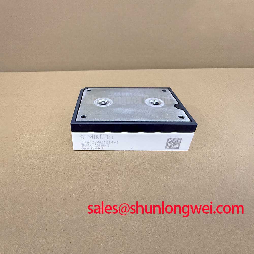
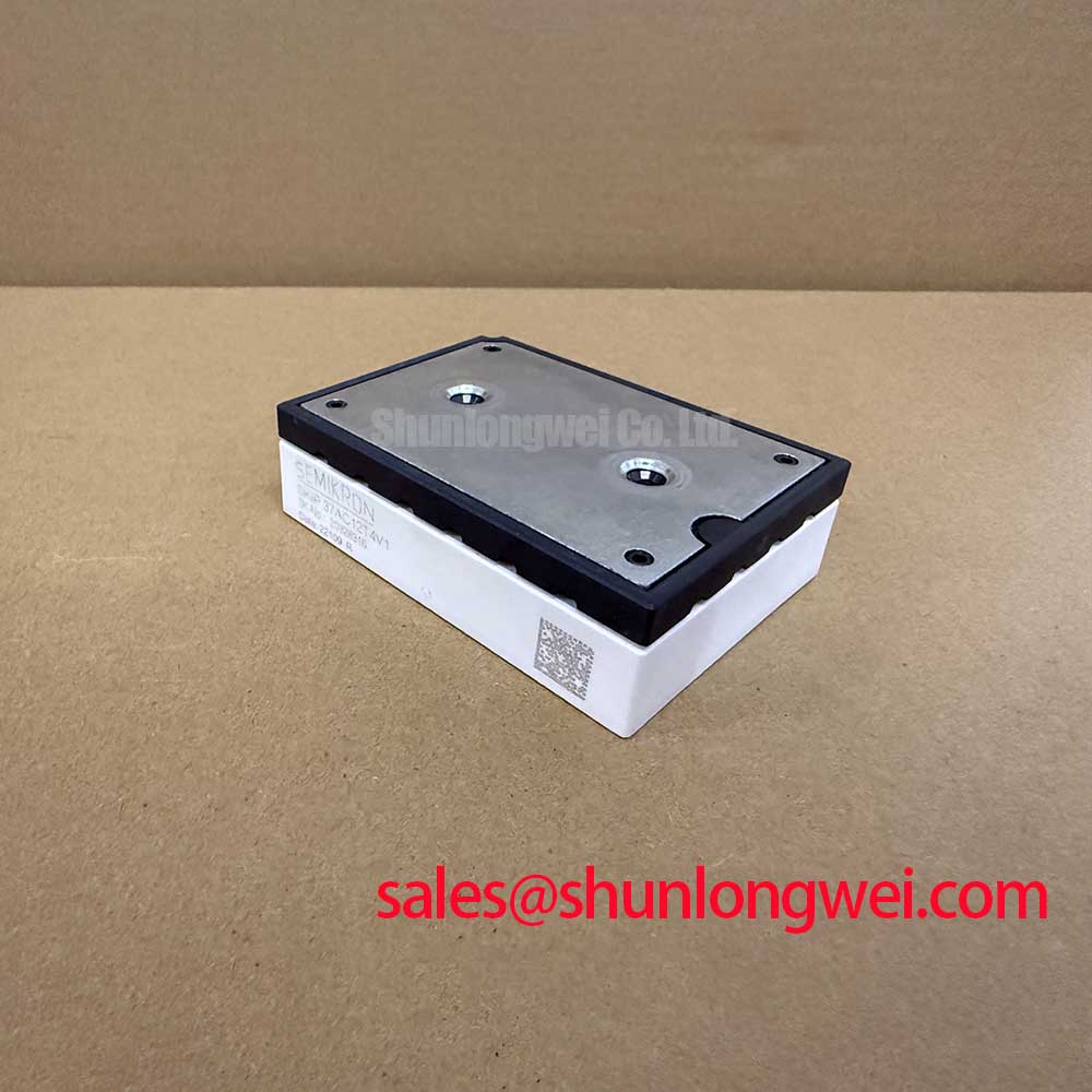
Incoming quality verification of high-power converter stages starts at the bench with precise static characterization. When testing the SKIIP37AC12T4V1 three-phase inverter topology, verifying internal gate insulation, collector-emitter leakage, and anti-parallel freewheeling diode drop ensures that only defect-free silicon enters production. Designed for demanding applications such as electric material handling equipment and industrial forklift low-voltage traction, the module is rated for a collector-emitter breakdown voltage of VCES = 1200 V at Tj = 25 °C and a nominal continuous collector current of ICnom = 75 A (Official Datasheet Specification). In battery-fed industrial vehicle traction, low stray inductance inverter design is essential to manage severe current transitions during rapid acceleration and abrupt stall conditions.
Under severe fault conditions, such as direct motor phase-to-phase shorts (Type I) or ground faults occurring while the switch is already conducting (Type II), current through the silicon can ramp rapidly toward the repetitive peak rating of ICRM = 225 A (Official Datasheet Specification, defined as 3 × ICnom). The SKIIP37AC12T4V1 provides a short-circuit withstand time of tpsc = 10 µs under conditions of VCC = 800 V, VGE ≤ 15 V, and Tj = 150 °C (Official Datasheet Specification). If an overcurrent trip abruptly cuts off gate drive voltage during this state, parasitic loop inductance produces an inductive kick that can breach the 1200 V barrier.
To suppress transient overvoltages, the gate drive circuitry must implement an active desaturation detection network paired with a two-stage soft turn-off (2S-STO) sequence. Rather than slamming the gate voltage from +15 V directly to -8 V or 0 V, the driver lowers the gate potential to an intermediate clamp level (such as +7 V) for 2 to 3 µs before final turn-off. This controlled step forces the collector current to ramp down at a manageable rate, keeping peak voltage excursion within the safe operating area (SOA). When conditioning raw phase current signals for hardware-level trip comparators, integrating ADI High Precision Current Sense Amplifiers provides the required low-latency feedback necessary to initiate desaturation protection well inside the 10 µs envelope.
For low-voltage, compact material-handling architectures where lower current ratings or alternate topologies are sufficient, engineers often benchmark this unit against alternative configurations such as the SKIIP 31 NAB 063 T1 during early prototype phase evaluation.
💡 Bench Tip: Prior to dynamic testing, ground all gate and auxiliary emitter pins using ESD-safe conductive foam. Measure the cold forward voltage across each freewheeling diode branch using a precision four-wire DMM set to 10 mA test current. A typical forward drop should register symmetrically across all six legs. Any module exhibiting an imbalance greater than 35 mV across phases under identical ambient conditions should be isolated for gate-leakage inspection.
Regenerative DC-Bus Voltage Surge Dissipation during Rapid Machine Deceleration
Electric forklifts and reach trucks generate substantial regenerative energy when stopping heavy mast loads or reversing drive wheel direction. This kinetic energy routes backward through the freewheeling diodes of the SKIIP37AC12T4V1, charging the DC-link capacitance. The module integrates freewheeling diodes rated at a continuous forward current of IF = 66 A under a heatsink temperature of Ts = 70 °C using standard thermal grease (Official Datasheet Specification). Managing this regenerative current requires a well-dimensioned dynamic braking circuit to prevent overvoltage tripping on the primary DC rail.
The module delivers a continuous collector current rating of IC = 73 A at Ts = 70 °C with thermal grease conductivity of λpaste = 0.8 W/(mK), which scales up to IC = 86 A at Ts = 70 °C when utilizing high-performance thermal interface material with λpaste = 2.5 W/(mK) (Official Datasheet Specification). These thermal dissipation thresholds dictate the switching frequency trade-offs in traction inverters. Operating at higher carrier frequencies (12 kHz to 16 kHz) eliminates audible motor hum in indoor warehouse operations but increases switching losses, requiring calculated current derating. Conversely, lowering switching frequencies to 4 kHz to 8 kHz lowers total losses, preserving current margin during prolonged hill-climb and mast-lift sequences.
To maintain DC-bus stability during sudden regenerative surges, the DC link relies on high-capacitance, low-ESR smoothing banks. Utilizing rugged Film Capacitors in High Ripple Current DC-Link Applications minimizes high-frequency ripple and absorbs localized commutation energy before braking choppers switch energy into external ballast resistors. For larger forklift chassis that segregate the traction inverter from auxiliary hydraulic pump drives, standard half-bridge power modules such as the SKM100GB124D are frequently integrated to manage independent braking chopper or lift-actuator sub-circuits.
Optocoupler vs Digital Coreless Transformer Isolation in High-Voltage Switching
Galvanic isolation between the micro-controller logic domain and the high-side IGBT gates is critical for operator safety and control signal fidelity. The SKIIP37AC12T4V1 provides an internal isolation test voltage rating of Visol = 2500 V AC (sinusoidal 50 Hz, 1 minute duration) (Official Datasheet Specification). In electric vehicle drive systems subjected to continuous battery charging cycles and inductive switching spikes, maintaining barrier integrity across years of field duty is non-negotiable.
High-voltage switching transitions generate common-mode noise across parasitic capacitances. If the gate driver isolator lacks sufficient Common-Mode Transient Immunity (CMTI), steep voltage transients can cause false pulse generation, resulting in catastrophic shoot-through. While traditional optocouplers offer cost-effective isolation, their current transfer ratio (CTR) degrades over time under high operating temperatures, leading to propagation delay drift. In contrast, digital isolators utilizing coreless micro-transformers or capacitive isolation barriers achieve CMTI ratings exceeding 100 kV/µs, delivering sub-nanosecond pulse width distortion and stable timing over the full operating temperature range.
⚠️ Field Alert: In traction motor drives operating with negative gate-emitter bias (typically -5 V to -8 V for turn-off), inspect PCB layout clearance around the control spring/pin landing pads. Stray inductive coupling between phase output copper and high-impedance gate traces can introduce differential noise. Gate-emitter traces must be routed as tightly coupled differential pairs directly to the driver output pins to prevent spurious conduction during rapid di/dt transitions.
Field diagnosis techniques and failure modes regarding common-mode gate disruption are documented extensively in the Field Engineer’s Handbook, which outlines isolation resistance benchmarks and bench diagnostic routines for returned power units.
Baseplate Convexity Compensation and Screw Tightening Sequence Guidelines
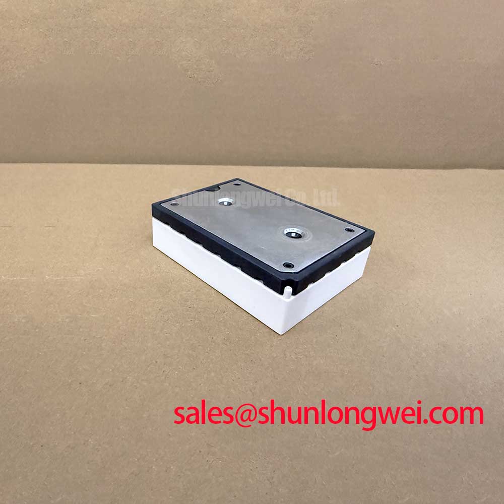
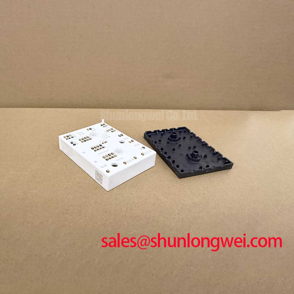
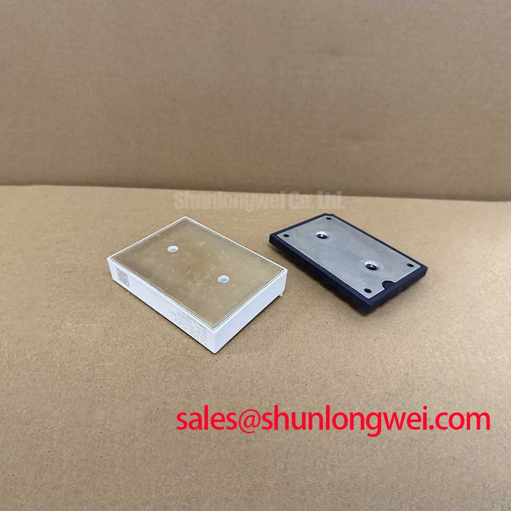
The SKIIP37AC12T4V1 utilizes a pressure-contact, solder-free spring connection architecture that mounts directly onto an engineered heatsink. Thermal transfer efficiency depends heavily on the physical contact uniformity between the module base substrate and the heatsink surface. Imperfections in heatsink planarity or incorrect torque application can cause localized ceramic substrate cracking or excessive thermal resistance hotspots.
Heatsink preparation requires a surface flatness tolerance within 20 µm across a 100 mm span, with a surface roughness of Rz ≤ 6.3 µm (General Industry Design Consideration). Apply a uniform layer of thermal interface material (TIM) between 50 µm and 100 µm in thickness using a calibrated silk-screen stencil or precision roller. Applying excessive paste acts as a thermal insulator, while insufficient paste leaves micro-voids containing trapped air.
| Parameter Description | Symbol / Condition | Official Value | Unit |
|---|---|---|---|
| Collector-Emitter Voltage | VCES (Tj = 25 °C) | 1200 | V |
| Nominal Collector Current | ICnom (Continuous DC) | 75 | A |
| Continuous Collector Current (Std TIM) | IC (Ts = 70 °C, λ = 0.8 W/mK) | 73 | A |
| Continuous Collector Current (High TIM) | IC (Ts = 70 °C, λ = 2.5 W/mK) | 86 | A |
| Repetitive Peak Collector Current | ICRM (3 × ICnom) | 225 | A |
| Short-Circuit Withstand Time | tpsc (VCC = 800 V, VGE ≤ 15 V, Tj = 150 °C) | 10 | µs |
| Diode Forward Current | IF (Ts = 70 °C, λ = 0.8 W/mK) | 66 | A |
| Isolation Voltage | Visol (AC 50 Hz, 1 min) | 2500 | V |
When fastening the module to the cooling assembly, follow a sequential diagonal cross-tightening protocol. Hand-tighten all mounting screws until light contact is established across all corners. Using a calibrated torque screwdriver, tighten diagonally opposing pairs in a two-stage process: first to 50% of the target mounting torque, and finally to the final assembly torque of 2.0 to 2.5 N·m (Typical Starting Point for standard M4 mounting hardware). This sequential clamping compensates for internal substrate convexity, spreading the thermal grease evenly across the interface without inducing mechanical shear stress in the DBC ceramic substrate.