
Content last revised on September 10, 2026
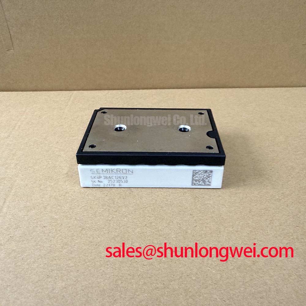
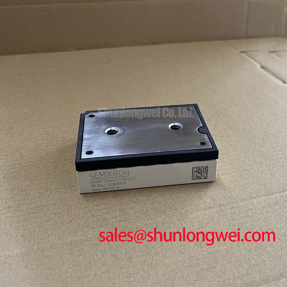
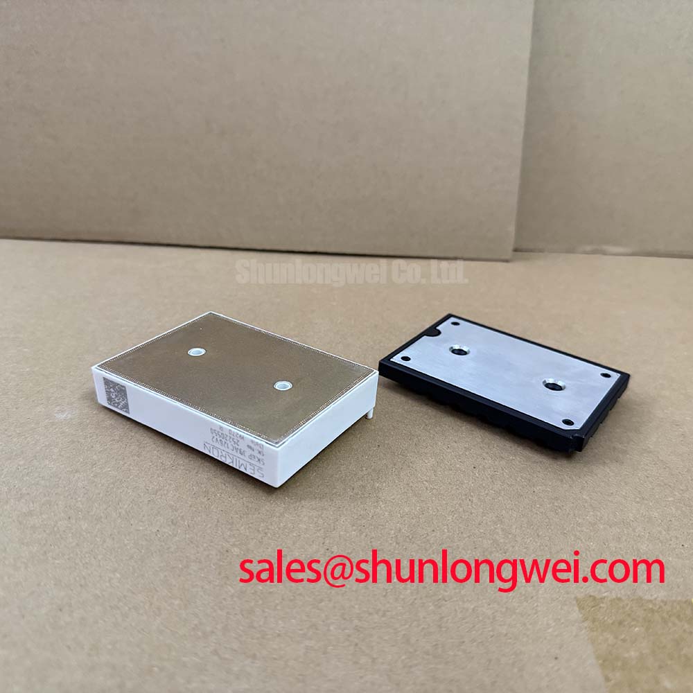
Semikron SKiiP39AC126V2 MiniSKiiP 3 IGBT Module: High-Reliability Power Control for 30 kW Motor Drives
As a professional electronic component distributor, we support your engineering decisions with precise data. The SKiiP39AC126V2 utilizes solder-free spring contact technology to eliminate thermal cycling solder fatigue, offering a low IGBT junction-to-sink thermal resistance of 0.3 K/W. Featuring a 1200V blocking voltage and 140A nominal current, this 3-phase bridge inverter module provides an exceptionally reliable interconnect interface for high-efficiency power converters. What is the primary benefit of its pressure-contact design? Solder-free spring contacts eliminate thermal fatigue to ensure long-term system reliability. For 30 kW industrial motor drives requiring high thermal fatigue resistance, this 1200V module provides the ultimate solder-free interconnect reliability.
Key Parameter Overview
Decoding the Specs for Enhanced Thermal Reliability
The technical parameters of the SKiiP39AC126V2 are structured to support detailed engineering evaluation. All parameters are compiled from official manufacturer datasheets to assist in your system-level design calculations.
| IGBT - Inverter Maximum Ratings | |||
|---|---|---|---|
| Parameter | Conditions | Value | Unit |
| VCES | Tj = 25 °C | 1200 | V |
| IC | Ts = 25 °C (70 °C) | 157 (118) | A |
| ICnom | Nominal collector current | 140 | A |
| ICRM | tp = 1 ms | 280 | A |
| IGBT - Inverter Characteristics (Tj = 25 °C unless specified) | |||
| VCE(sat) | ICnom = 140 A, Tj = 25 °C (125 °C) | 1.7 (2.0) | V |
| Rth(j-s) | per IGBT (to heatsink) | 0.3 | K/W |
| Eon / Eoff | ICnom = 140 A, Tj = 125 °C, VCC = 600 V | 19.9 / 17.2 | mJ |
| Inverse Diode - Maximum Ratings & Characteristics | |||
| IF | Ts = 25 °C (70 °C) | 167 (124) | A |
| VF = VEC | IFnom = 140 A, Tj = 25 °C | 1.5 | V |
| Rth(j-s) | per diode (to heatsink) | 0.4 | K/W |
| Temperature Sensor & Mechanical Data | |||
| Rts | 3% tolerance, Tr = 25 °C (100 °C) | 1000 (1670) | Ω |
| Mass | Net module weight | 95 | g |
Download the SKiiP39AC126V2 datasheet for detailed specifications and performance curves.
Application Scenarios & Value
Achieving System-Level Benefits in High-Frequency Power Conversion
In heavy-duty industrial environments, engineers face severe challenges during system startups. When driving a high-inertia motor, inrush current surges place extreme thermal and electrical stress on the power semiconductor stage. The SKiiP39AC126V2, designed inside a compact MiniSKiiP 3 package, is primarily used in 3-phase inverter systems up to 45 kVA, supporting typical motor power ratings of 30 kW.
For system topologies requiring lower current handling or alternative footprints, engineers might evaluate options like the SKiiP 25AC126V1. However, the 140A nominal current capacity of this module delivers the critical thermal margin and headroom required for 30 kW motor power stages under continuous load. This capacity makes it a preferred solution for modern variable speed drives and uninterruptible power supplies (UPS) that demand high reliability. By integrating this module, systems can comfortably satisfy stringent efficiency metrics and industry compliance standards such as IEC 61800-3.
To understand how this package class performs compared to traditional module layouts, engineers can read our comparative analysis of the Semikron vs Infineon IGBT Showdown. For detailed gate control and layout considerations, reference our guide on IGBT thermal management and circuit topologies.
Technical Deep Dive
A Closer Look at the Solder-Free Spring Contact Design for Long-Term Reliability
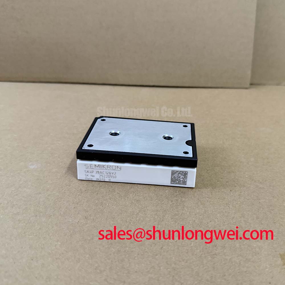
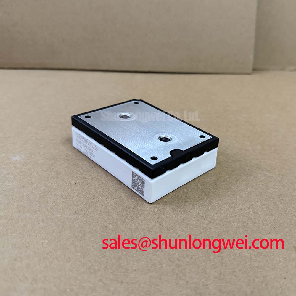
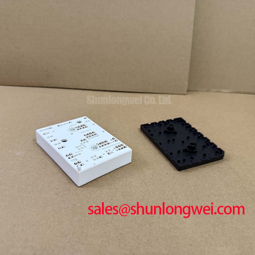
The structural layout of the SKiiP39AC126V2 centers around Semikron's proprietary pressure-contact technology, which relies on mechanical pressure to establish electrical connections rather than soldered pins. To explain this engineering design, we can use two distinct physical analogies:
- The Thermal Expressway Analogy: A low junction-to-sink thermal resistance Rth(j-s) of 0.3 K/W acts like an unrestricted multi-lane highway for heat. It allows the thermal energy generated during high-frequency switching to escape instantly from the silicon chip directly to the heatsink. Without the physical barriers of thick solder layers, heat is dissipated rapidly, reducing peak thermal stress.
- The Suspension System Analogy: The spring contacts act like the heavy-duty suspension of an off-road vehicle. During rapid temperature fluctuations, materials expand and contract at different rates, creating structural strain. Traditional solder joints eventually crack under this stress. The flexible spring contacts absorb this thermal expansion, maintaining a gas-tight, vibration-resistant electrical connection over thousands of power cycles.
Complementing the mechanical structure is the implementation of fast trench IGBTs paired with robust freewheeling diodes in Controlled Axial Lifetime (Semikron CAL Diode) technology. This diode design minimizes reverse recovery current peaks, drastically lowering switching losses and curbing high-frequency electromagnetic interference (EMI). The integrated temperature sensor (Rts) provides real-time feedback of the substrate temperature, allowing control systems to initiate protective de-rating before the silicon exceeds its maximum operating temperature. Learn more about these packaging advantages by studying Semikron SKiiP® Technology.
Frequently Asked Questions
Addressing Core Engineering and Implementation Challenges
How does the low Rth(j-s) of 0.3 K/W impact heatsink selection in industrial designs?
The low thermal resistance minimizes the temperature gradient between the IGBT junction and the cooling surface. This high thermal transfer efficiency allows engineers to select smaller, lighter passive or forced-air heatsinks, saving valuable physical space within the inverter cabinet while safely protecting the module from overtemperature failures.
What is the typical motor power rating for this module?
It is optimal for driving typical motor power loads of thirty kilowatts.
How do the CAL freewheeling diodes benefit high-frequency switching operations?
The CAL (Controlled Axial Lifetime) diodes feature an exceptionally soft reverse recovery wave. This soft-switching behavior significantly reduces voltage spikes (di/dt ringing) during turn-off phases. As a result, it reduces the size and cost of the necessary snubber circuits and makes it much easier to meet industrial EMI compliance standards.