
Content last revised on November 2, 2026
2MBI75S-120 Incoming Inspection and Key Ratings
- Isolate the power assembly, discharge the DC link, and verify absence of voltage before checking the 2MBI75S-120 main terminals.
- Match collector, emitter, and gate connections to the terminal diagram before recording cold diode-check readings.
- Check terminal seating, busbar alignment, and heatsink contact without using fasteners to pull misaligned parts together.
- Separate gate-driver and power-stage measurements so connected circuitry does not obscure incoming inspection results.
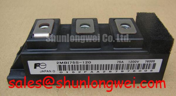
The Fuji Electric 2MBI75S-120 is an IGBT module rated at 1200 V and 75 A. For incoming inspection, distinguish absolute ratings from characteristics measured under specified bias conditions. A handheld meter can support comparative screening, but it cannot reproduce rated-current saturation voltage or establish high-voltage blocking capability.
| Official Specification | Test Condition | Value |
|---|---|---|
| Collector-emitter voltage, VCES | Rated limit | 1200 V |
| Gate-emitter voltage, VGES | Rated limit | ±20 V |
| Continuous collector current, IC | Case temperature 80°C | 75 A |
| Pulsed collector current, ICP | Pulse duration 1 ms | 150 A |
| Maximum power dissipation, PC | Rating subject to thermal operating limits | 600 W |
| Collector-emitter saturation voltage, VCE(sat) | IC 75 A; VGE 15 V | 2.6 V typical; 3.0 V maximum |
| Gate-emitter threshold voltage, VGE(th) | IC 75 mA; VCE 20 V | 5.5 V minimum; 8.5 V maximum |
| Diode forward voltage, VF | Junction temperature 125°C; IF 75 A; VGE 0 V | 2.0 V typical |
| IGBT junction-to-case thermal resistance | Rth(j-c) | 0.208°C/W |
| Diode junction-to-case thermal resistance | Rth(j-c) | 0.38°C/W |
For integration, consult the manufacturer’s terminal drawing, dimensional drawing, mounting instructions, transient thermal curves, and insulation-test conditions.
2MBI75S-120 Thermal-Electrical Optimization: Dynamic Power Loss Dissipation and Multi-RC Practical Tuning
Separate IGBT losses from diode losses before estimating junction temperature during a pulsed overload. The official 0.208°C/W IGBT and 0.38°C/W diode junction-to-case resistances describe thermal paths; neither is a complete transient thermal model. The 150 A for 1 ms pulse rating must not be interpreted as permission for unrestricted repetitive overload.
Engineering Calculation: a multi-RC thermal model represents transient impedance as Zth(t) = Σ Ri[1 − exp(−t/τi)], with the resulting temperature rise calculated from the applied loss history. Its resistance and time-constant terms must come from applicable transient thermal data or a validated model, rather than an arbitrary division of the steady-state thermal resistance. Repetitive pulses require residual heating from earlier pulses to be included.
Design Consideration: measure case temperature at a repeatable location and capture current, collector-emitter voltage, and switching timing under the intended operating conditions. Combine conduction and switching losses with the cooling assembly’s measured behavior. The 600 W maximum dissipation rating is not an allowable continuous heat load for an unspecified heatsink.
When adjusting gate resistance, designers should compare switching energy, overshoot, and ringing together. Additional damping can reduce oscillation while increasing switching loss. Select the final resistance through controlled measurements with the actual driver and interconnects, not from the current rating alone.
2MBI75S-120 Circuit Protection & Reliability: Transmission Line Impedance Mismatch
Measure inverter-output and motor-terminal waveforms separately when investigating cable-related voltage peaks. Design Consideration: a traveling wave reflects when cable and load impedances differ; an ideal open termination can double the incident voltage step, but this is not a guaranteed peak for every drive or a 2MBI75S-120 characteristic.
For compatibility assessment in a heavy-duty variable-frequency AC motor drive, designers should evaluate cable length, edge rate, motor insulation requirements, and output-filter behavior together. A dv/dt filter or choke requires system-specific inductance, capacitance, damping, and current capability. Confirm its effect at the motor terminals as well as at the inverter.
Design Consideration: distinguish cable reflection from local commutation overshoot. Freewheeling-diode reverse recovery interacts with loop inductance and switching speed; the static 2.0 V diode specification does not establish recovery softness. Shorten the commutation loop where practical and evaluate snubber damping against measured ringing and component heating. Mastering Power System Dynamics provides related context for stray-inductance and snubber assessment.
Fuji Electric’s RC-IGBT module information concerns a separate product family; it does not establish this module’s construction or recovery performance. Likewise, an auxiliary switching position involving 2MBI25L-120 requires its own circuit assessment rather than an assumed role as an input rectifier.
Benchtop Assembly Checks: Mitigating Mechanical Stress on 2MBI75S-120
Check screw engagement and busbar seating before applying terminal tightening force. Design Consideration: excessive screw length can bottom out, while insufficient engagement can compromise the joint. Use the specified fastener, washer arrangement, and torque from the applicable mechanical instructions; do not infer them from another module with a similar outline.
Support the busbar independently so its weight and alignment do not lever against the power terminals. Inspect mating surfaces for contamination and uneven seating, and preserve the required electrical clearances after assembly. These checks address externally applied stress without asserting an undocumented internal leadframe or copper-joint construction.
During controlled operation, compare terminal temperature rise and voltage drop under repeatable load conditions. An abnormal joint reading warrants inspection of contact pressure, surface condition, and alignment; it does not by itself identify an internal fracture. Thermal cycling and vibration assessments belong to the complete mounting assembly.
For cross-model evaluation, 6MBI75S-120-2 should be compared by circuit configuration, terminal assignment, mounting geometry, driver requirements, and thermal behavior—not treated as a drop-in replacement. Fuji Electric’s SiC semiconductor resources provide broader technology context, not replacement approval for this module.
Transient Dynamics & Electrical Design: Cold-State Main Terminal Impedance on 2MBI75S-120
Record diode-check polarity, instrument model, module temperature, and whether external circuitry remains connected. With the gate held at emitter potential, compare the expected antiparallel-diode conduction direction against the terminal diagram. Repeat measurements consistently across corresponding switch positions; charge retained on a floating gate can alter the apparent collector-emitter reading.
💡 Bench Tip: Use ESD-controlled handling and keep the gate referenced to its emitter during cold comparisons to avoid charge-dependent readings.
Design Consideration: a meter’s forward-voltage result is a low-current screening observation, not a verification of the official diode voltage at 75 A and 125°C. Likewise, the 5.5–8.5 V gate-threshold range describes conduction onset at the specified test point, not the gate voltage required for rated-current operation.
Investigate unexpected gate-emitter conduction with a current-limited measurement after disconnecting the driver. Gate leakage acceptance requires the manufacturer’s leakage limits and test conditions; an ordinary resistance reading cannot establish compliance. Check the insulation-test voltage, duration, terminal grouping, and permissible leakage against the manufacturer’s procedure before using dielectric test equipment. The 1200 V collector-emitter rating is not a terminal-to-base insulation-test rating.
Keep cold screening results separate from powered acceptance records. If static comparisons are consistent, proceed under the equipment’s controlled commissioning procedure and verify gate waveform, switching overshoot, and protection response before restoring operational load.