


Content last revised on October 25, 2026
Assembly Integrity & Layout Architecture: Implementing Main Power Terminal Contact Resistance for 6MBI75S-120-2
Isolate the DC link, verify that stored energy has discharged, and measure each accessible main-terminal joint before disturbing the busbar assembly on the 6MBI75S-120-2. Recording the original joint condition helps separate an external connection problem from a suspected semiconductor fault and preserves useful evidence before cleaning or reassembly changes the contact surfaces.
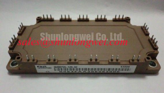
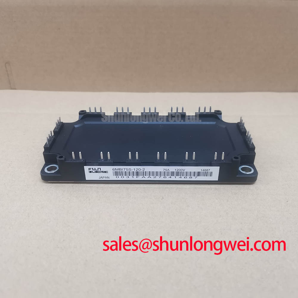
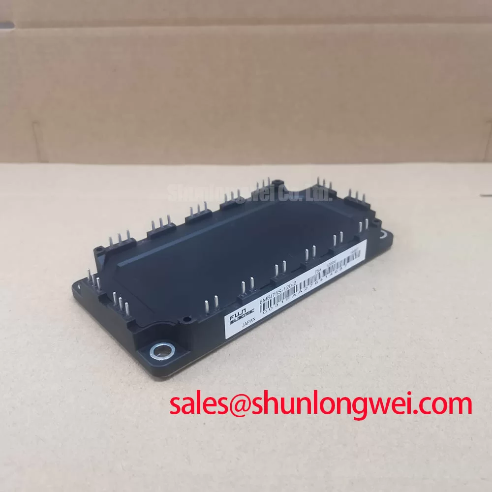
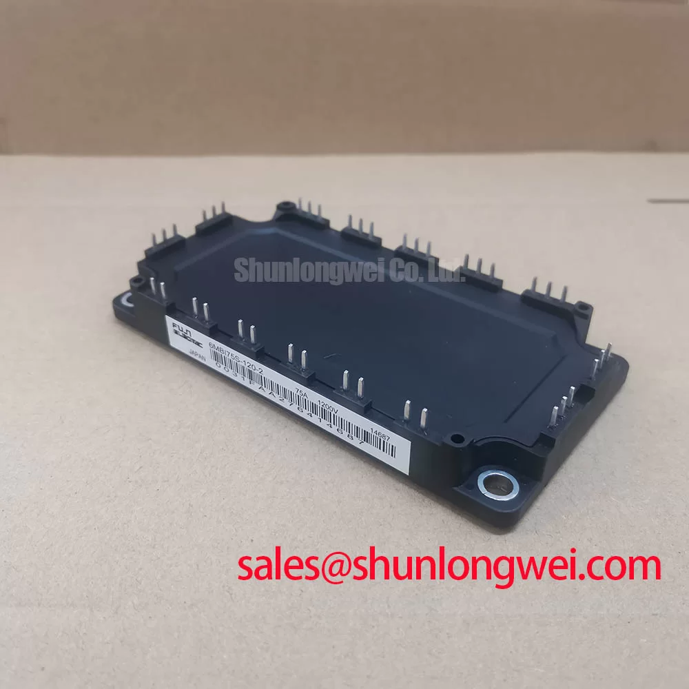
The 6MBI75S-120-2 is a Fuji Electric IGBT module with a 1200 V voltage rating and a 75 A current rating (Official Specification). Its supplied package designation is Fuji Power Module. These ratings establish the initial electrical selection boundary; the integration assessment also needs to address terminal connections, gate-drive behavior, thermal response, and mounting geometry.
Position micro-ohmmeter sense probes directly across the bolted interface under examination, rather than across a length of busbar that adds unrelated conductor resistance. As a Design Consideration, a four-wire measurement is useful because it separates the voltage-sensing path from the instrument’s current leads. The assembly should be electrically isolated so parallel paths do not conceal a poor connection or expose connected electronics to an unsuitable test current.
Record probe locations, joint temperature, instrument settings, and the mechanical state of the connection. Repeat measurements with consistent probe pressure and compare equivalent joints under comparable conditions. A universal contact-resistance pass limit should not be assigned to this module: the acceptance criterion belongs to the qualified terminal assembly, including its contact area, surface condition, fasteners, and busbar arrangement.
Engineering Recommendation: inspect mating surfaces for contamination, uneven witness marks, displaced hardware, and busbar loading that pulls a terminal away from its natural alignment. Clean and assemble the interface using procedures compatible with its surface finish. Increasing bolt torque to compensate for a high resistance reading can conceal the actual contact problem while introducing mechanical stress.
After controlled re-energization, thermographic comparison can help locate uneven heating across electrically comparable connections. Camera angle, surface emissivity, nearby heat sources, and load history affect the image, so an isolated hot region is a reason for further investigation rather than proof of a specific defect. Correlate the thermal pattern with joint measurements and actual current distribution before deciding which interface needs corrective work.
Layout clearance is also an assembly issue. As a Design Consideration, verify spacing between energized hardware, adjacent conductors, and the grounded chassis against the equipment’s applicable insulation requirements. Support external conductors independently where practical, and preserve tool access so maintenance does not require bending a terminal or levering against the module housing.
Preventing Spurious Faults: Gate Drive Resistance Calibration for 6MBI75S-120-2
Trace the external turn-on and turn-off gate-current paths before changing resistance on a legacy driver board. Engineering Recommendation: identify the driver output stage, any steering diodes, the gate return, and the protection shutdown path as one circuit. A resistor value copied from another module does not establish equivalent switching behavior because the driver, interconnects, and semiconductor characteristics all influence the waveform.
For an assessment involving the 6MBI100U4B-120, compare the actual electrical and mechanical interfaces rather than treating the shared manufacturer as evidence of interchangeability. The following table separates the established identity of the 6MBI75S-120-2 from the documentation checks required for a different part.
| Selection item | 6MBI75S-120-2 | 6MBI100U4B-120 comparison |
|---|---|---|
| Manufacturer | Fuji Electric | Fuji Electric |
| Voltage rating | 1200 V — Official Specification | Consult datasheet |
| Current rating | 75 A — Official Specification | Consult datasheet |
| Package designation | Fuji Power Module | Consult package drawing |
| Gate-drive compatibility | Assess against the installed driver | Compare gate characteristics and switching test conditions |
| Mechanical compatibility | Check terminal layout and mounting interface | Compare dimensions, clearances, and terminal positions |
As a Design Consideration, increasing gate resistance generally trades switching speed against switching loss, but the useful balance must be established in the installed circuit. Observe gate-emitter voltage and collector-emitter voltage with suitable probes and controlled test conditions. Separate turn-on and turn-off adjustments, where the driver supports them, can help distinguish excessive switching-edge excitation from an unnecessarily slow transition.
Miller-induced gate movement deserves particular attention during complementary-device switching. Keep the gate-current loop compact and avoid sharing its return path with high-current power connections wherever the circuit architecture permits. If the existing driver employs negative off-state bias or a Miller clamp, evaluate its operation against the module’s permitted gate limits and measured transients. Neither technique should be added as an assumed requirement of this model.
Dead time should cover the relevant propagation delays and device turn-off behavior across operating conditions. Engineering Recommendation: check complementary gate interlocking at the driver outputs, including enable transitions and fault shutdown, rather than relying only on controller timing settings. Excessive dead time also has operating consequences, so establish the timing from measured switching behavior rather than assigning a generic buffer.
Pro Tip: Keep outgoing and return power paths closely coupled and geometrically balanced to reduce turn-off overshoot, then validate the resulting voltage margin with a controlled double-pulse test.
For topology coordination, a separate stage involving the 6MBI20GS-060 needs its own device-role and rating assessment; it should not be classified as a front-end rectifier simply because it appears elsewhere in the power assembly. Likewise, Fuji Electric Brake Chopper IGBT Modules provides context for a distinct switching function, not evidence that the 6MBI75S-120-2 has that configuration. Any MOV-based absorption network belongs to the surrounding system and requires coordination with its actual transient energy and protection behavior.
Preventing Spurious Faults: Evaluating Thermal Capacitance vs Heat Sink Guidelines for 6MBI75S-120-2
Reconstruct the load pulse and the temperature at the module’s case reference location before assessing a pulsed overload. As a Design Consideration, a heatsink temperature reading alone cannot describe the rapid junction excursion that occurs during a short, high-loss event. The thermal path stores and releases heat over different time scales, so pulse duration and the preceding load history matter alongside average dissipation.
An Engineering Calculation can estimate junction temperature by combining the case-temperature boundary with the loss waveform and the module-specific transient junction-to-case thermal response. For a rectangular loss pulse under the appropriate boundary conditions, the junction-to-case temperature rise is the pulse power multiplied by the transient thermal impedance at that pulse duration. Repeated pulses require accounting for residual heating rather than restarting the calculation from a cold state each cycle.
A multi-RC thermal model can represent this time-dependent response when its coefficients reproduce the relevant manufacturer thermal-impedance data. Use the model’s intended network arrangement and boundary conditions; coefficients from different network forms are not directly interchangeable. Avoid assigning an unrelated module’s thermal capacitance to the 6MBI75S-120-2 merely because its voltage or current rating appears similar.
Engineering Recommendation: build the loss estimate from the actual conduction intervals and switching events, using device data under matching conditions wherever available. Include the operating sequence that produces the highest accumulated heating, not just an isolated pulse. Compare the resulting peak junction estimate with the permitted operating boundary and retain the assumptions with the equipment’s validation record.
The 75 A rating should therefore be assessed together with cooling and waveform conditions when evaluating compatibility with an industrial inverter welder or medium-frequency induction-heating power supply. These are potential integration examples, not declared application approvals. Their intermittent or changing loads make the distinction between steady thermal resistance and transient thermal impedance especially relevant.
For broader treatment of the surrounding drive and cooling interfaces, IGBT Design & Integration provides related engineering context. Manufacturer family descriptions also need to remain distinct: Fuji Electric RC-IGBT Modules describes a separate product technology and should not be used to assign internal construction or thermal behavior to this model.
6MBI75S-120-2 Operational Boundaries: Evaluating Baseplate Convexity Inspection Limits
Check the module’s mounting surface and the heatsink mating face separately before interpreting a gap or contact pattern. As a Design Consideration, the inspection method should distinguish overall curvature from local damage, debris, and machining features. Use clean reference tooling and controlled support conditions so the measurement does not introduce the deformation it is intended to detect.
Do not assume that a visibly non-flat surface is automatically defective. Some mounting interfaces are specified with a controlled profile, and acceptance depends on the applicable mechanical drawing and assembly instructions. Record the location and direction of measured deviation rather than reducing every observation to a single flatness number. Also inspect the heatsink for raised edges around mounting holes and residue from the previous installation.
Engineering Recommendation: select and apply the thermal interface material according to the qualified module-and-heatsink assembly process. The aim is continuous contact with controlled displacement of excess material, not an arbitrary universal film thickness. A contact-transfer inspection during process qualification can reveal dry regions, uneven spreading, or a localized obstruction without treating the resulting pattern as a direct junction-temperature measurement.
Use a calibrated torque tool and the specified tightening sequence. Where the assembly instructions call for progressive diagonal tightening, bring the fasteners down in stages so the interface seats evenly. Keep mounting-fastener requirements separate from main-terminal requirements, and check that washers, thread engagement, and heatsink support match the approved assembly.
Press-pack loading, disc-spring pressure calibration, and double-sided cooling procedures should not be transferred to this Fuji Power Module without an applicable mechanical specification. During final assembly, keep busbars from imposing bending loads, preserve the required electrical clearances, and inspect the seated interface before reconnecting power. Retain the measured surface condition, tightening record, and thermal-interface application details so subsequent temperature changes can be compared with a documented installation.