Shunlongwei Co. ltd.
IGBT Module / LCD Display Distributor
Customer Service
+86-755-8273 2562
IGBT Module / LCD Display Distributor
“Liquid crystal Display has become the mainstream of flat-panel TVs and computer display terminals. The research, design, production, inspection and other departments of liquid crystal displays and even consumers need to use some quantitative or qualitative methods and indicators to test the quality and characteristics of liquid crystal displays.
“
introduction
Liquid crystal display has become the mainstream of flat-panel TVs and computer display terminals. The research, design, production, inspection and other departments of liquid crystal displays and even consumers need to use some quantitative or qualitative methods and indicators to test the quality and characteristics of liquid crystal displays.
LCD TVs and LCD monitors are digital display terminals. In order to be compatible with current computer graphics cards, computer monitors generally retain analog VGA interfaces. As household LCD TVs, VGA interfaces are also generally reserved to receive analog VGAs. Display signal. The signal generators used in some of the current LCD white balance adjustment and detection equipment all adopt the method of transmitting signals from the AV signal interface, VGA interface or YPbPr TV interface of the LCD TV and monitor to the LCD screen. The control circuit of the screen is again converted into a digital signal and transmitted to the digital scanning circuit of the LCD screen. During this process, the digital signal generated by the signal generator undergoes D/A conversion, transmission and A/D conversion, which will inevitably bring the final image signal. degree of distortion and loss.
Therefore, the purpose of this paper is to design a signal generator that outputs digital quantities and directly input digital signals through the LVDS interface of the LCD screen.
1. Interface of LCD screen
The receiving end of the signal generator developed in this paper is the “M220EW01V0″ model 22” widescreen 16:9 LCD screen produced by AUOPTRONICS CORPORATION.
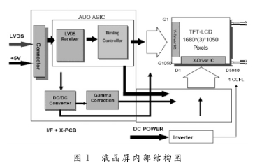
The external interface of the logic control and driving circuit of the LCD screen is an LVDS interface. The internal logic circuit receives the differential signal input by LVDS and parses it into an image signal of LVTTL level, and is controlled by the internal timing controller to generate scanning signals in the X direction and the Y direction, and the LCD screen displays the image. Fig. 1 is the internal structure diagram of the liquid crystal screen.
The typical frame frequency of the LCD screen is 60 Hz, and the typical clock frequency is 72.1 MHz. The data format and sequence received by the LVDS interface are shown in Figure 2 and Figure 3.
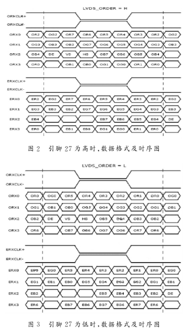
It can be seen that the timing of receiving data is different by setting pin 27 to high level or low level. In this article, pin 27 is directly connected to GND and set to low level.
The above description is the basis for generating image timings by programming in VHDL language.
2. Overall system design
2.1 Overall structure design of the system
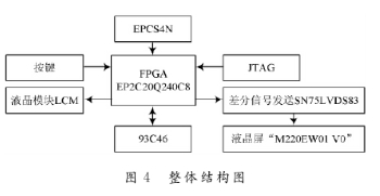
In this paper, Altera’s CYCLONEⅡ series EP2C20Q240C8 FPGA is used as the main control chip, programmed with VHDL hardware description language, and the SN75LVDS83 chip of TI company is used as the differential signal transmitter to send the video image signal generated by the system to the LVDS interface of the LCD screen. The system also includes a key control input module, which is used to select the displayed graphic mode and adjust the grayscale value; the LCM module YM1602C is used to display the status information of the system, such as the grayscale value of the image; the 93C46 data storage module based on the Microwire protocol is used for Storage system parameters; in addition, there are JTAG download interface circuit of FPGA, and EPCS configuration chip part for active configuration mode. The system structure is shown in Figure 4.
2.2 System Difficulty Design
The data input port of the LCD screen is an LVDS interface, and LVDS technology is used when transmitting image data. LVDS (Low Voltage Differential Signaling) is a low-swing differential signal transmission technology, which enables signals to be transmitted at a rate of hundreds of Mb/s on differential PCB line pairs or balanced cables. The current-driven output achieves low noise and low power consumption.
The SN75LVDS83 chip produced by TI is an LVDS sending chip used for flat-panel TV video transmission. It is powered by 3.3 V and has a typical power consumption of 250 mW. When there is no signal transmission, the power consumption is less than 1 mW. Shift register, a 7x clock frequency multiplier, a total of 5 LVDS drivers, can transmit 28 b single-ended TTL or LVTTL data synchronously after connecting a balanced cable.
The image RGB data and synchronization signal generated by FPGA are input into the SN75LVDS83 chip in parallel, and the pin connection relationship between them is shown in Figure 5. The system adopts two SN75LVDS83 chips, which transmit RGB data of odd pixels and RGB data of even pixels respectively.
The operating frequency of FPGA and differential signal transmission circuit is very high. The clock frequency of FPGA is up to 50 MHz, and the differential signal is up to 350 MHz. Therefore, the design of anti-high-frequency interference of PCB is a difficulty in hardware design. In the PCB design, special attention was paid to the differential signal wiring of the LVDS interface, the isolation problem of the digital ground and the analog ground, and the analysis of signal integrity, and the impedance matching problem of the LVDS interface was solved at the same time.
3. System image generation design principle and experimental results
3.1 The principle of image generation design
The images designed in this paper are divided into three categories. The first category is pure color images, including pure red, pure green, pure blue and black and white images; the second category is square images, and the colors of each block are different; There are moving elements in the image.
When displaying the first type of image, as long as the RGB value is set to a certain combination value, the LCD screen will display a pure color image without changing. In this paper, the RGB value can also be modified according to the key input, so the displayed image is gray When displaying this type of image, the RGB value of each pixel on the surface of the LCD screen is the same; when displaying the second type of image, different RGB values are input according to the row counter and column counter to make the LCD screen surface The RGB values of pixels in different areas are different, but each frame of this type of image is the same, so it is a static image; in addition to changing the RGB value according to the row counter and column counter, the RGB value also changes according to time, which is the third The principle of class image generation.
3.2 Experimental results
Table 1 is the image and detection function realized by this system.
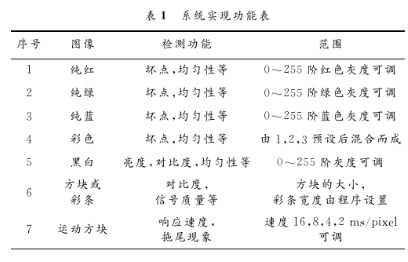
FIG. 6 is a color image of pure red, pure green and pure blue with adjustable gray value displayed on the LCD screen.
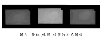
Figure 7 is a black-and-white interval nine-square image displayed on the liquid product screen.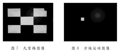
Figure 8 is a screenshot of a block moving image with adjustable speed. The displayed image is clear and jitter-free, the speed of the moving blocks in the moving image is adjustable and the motion is stable.
The test results show that the signal generator meets the design requirements and can provide stable image signals through the LVDS interface of the LCD screen.
4. Conclusion
The LCD test signal generator developed in this paper can generate various image signals required for testing LCD, and detect the characteristics and quality of the LCD screen through the displayed images. And the signal generator developed in this paper overcomes high-frequency interference in hardware design, and generates pure digital image signals. Compared with analog image signal generators based on AV, VGA or YPbPr signals, it has less distortion and loss, and the image The advantages of good quality can be applied to practical situations.
The Links: 2MBI300LB-060 LQ084V1DG43