
Content last revised on June 10, 2026
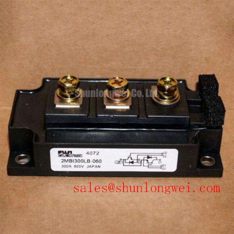
2MBI300LB-060 Fuji Electric 600V 300A Dual IGBT Module
The 2MBI300LB-060, a cornerstone of the Fuji Electric L-Series family, represents a high-efficiency 2-pack IGBT module designed for engineers who prioritize the reduction of switching and conduction losses in mid-voltage power systems. Operating with a Collector-Emitter Voltage (Vces) of 600V and a Continuous Collector Current (Ic) of 300A, this module is optimized for high-power density applications where thermal overhead is a critical constraint. By integrating a high-speed switching silicon structure with a soft-recovery Freewheeling Diode (FWD), it effectively mitigates EMI while maintaining superior efficiency across a wide range of switching frequencies.
Top Specs: 600V | 300A | Vce(sat) 2.10V (Typical)
Key Benefits: Optimized for low conduction loss; High-reliability dual-pack package.
One common engineering question regarding the 2MBI300LB-060 is how its saturation voltage influences overall system efficiency. The typical Vce(sat) of 2.10V ensures that conduction losses are kept to a minimum during the "on" state, which is particularly beneficial for PWM inverters and welding power supplies that operate under heavy duty cycles. For 200V-400V AC drive systems requiring optimized conduction efficiency, the 2MBI300LB-060 serves as a robust 300A foundation.
Key Parameter Overview
Functional Grouping of Technical Specifications for Design Precision
The following data is synthesized from official engineering documentation to assist in the validation of the 2MBI300LB-060 within specific circuit topologies.
| Absolute Maximum Ratings (Tc=25°C unless specified) | |
|---|---|
| Collector-Emitter Voltage (Vces) | 600V |
| Gate-Emitter Voltage (Vges) | +/- 20V |
| Continuous Collector Current (Ic) | 300A |
| Pulsed Collector Current (Icp) | 600A |
| Max Power Dissipation (Pc) | 1100W |
| Operating Junction Temperature (Tj) | +150°C |
| Electrical Characteristics (Typical Values) | |
|---|---|
| Collector-Emitter Saturation Voltage (Vce sat) | 2.10V (at Ic=300A) |
| Gate Threshold Voltage (Vge th) | 4.5V to 7.5V |
| Turn-on Time (ton) | 1.20 µs |
| Turn-off Time (toff) | 1.00 µs |
| Thermal Resistance Junction-to-Case (Rth j-c) | 0.11 °C/W (IGBT) |
Download the 2MBI300LB-060 datasheet for detailed specifications and performance curves.
Application Scenarios & Value
Maximizing Throughput in Industrial Power Conversion Topologies
The 2MBI300LB-060 excels in environments where high-current switching must be achieved with minimal thermal dissipation. In a typical Variable Frequency Drive (VFD) application, engineers face the challenge of managing heat during high-load motor startups. The low thermal resistance of 0.11 °C/W allows for more aggressive Thermal Management, ensuring that the module remains within the safe operating junction temperature even during transient overloads. Saturation voltage in this context is like the pressure drop in a valve; the lower typical Vce(sat) of the 2MBI300LB-060 ensures that more energy reaches the motor rather than turning into waste heat within the cabinet.
Beyond motor control, this module is a preferred choice for Uninterruptible Power Supplies (UPS) and Solar Inverters operating in the 600V class. Its soft-switching characteristics reduce the stress on the Snubber Circuit, allowing for a more compact and cost-effective overall design. For systems requiring even higher current handling within the same voltage class, the related 2MBI400VG-060 offers an increased Ic of 400A, while the 2MBI200VA-060 provides a scaled-down 200A alternative for lighter loads.
Integrating this module also supports compliance with modern energy efficiency standards, such as those found in high-frequency induction heating or medical MRI power stages, where Switching Loss directly impacts the total cost of ownership. For a broader understanding of how these components fit into modern architecture, consult our guide on IGBT modules as the backbone of high-efficiency systems.
Technical Deep Dive
Advanced Loss Suppression via the L-Series Trench Architecture
The 2MBI300LB-060 utilizes a refined Trench IGBT gate structure which significantly improves the carrier distribution across the drift region. This physical optimization is the primary driver behind the module's ability to maintain a low Vce(sat) without sacrificing Short-Circuit Withstand Time. For the design engineer, this means the module is "rugged by design," capable of surviving localized fault conditions that might lead to IGBT failure in less advanced silicon architectures.
Furthermore, the internal Freewheeling Diode (FWD) is specifically matched to the IGBT's switching speed. This reduces the reverse recovery current ($I_{rr}$), which is a major source of Switching Loss and electromagnetic noise. By minimizing these transients, the 2MBI300LB-060 simplifies the Gate Drive requirements and reduces the need for heavy EMI filtering. To visualize these principles in action, engineers may find our visual guide to IGBT working principles a valuable resource for system-level optimization.
FAQ
How does the low Rth(j-c) of 0.11 °C/W directly impact heatsink selection and overall system power density?
A lower Thermal Resistance means heat is transferred from the junction to the case more efficiently. For the 2MBI300LB-060, this allows engineers to either use a smaller heatsink to save space or drive higher currents through the module while maintaining a safe thermal margin, thereby increasing the system's power density.
What is the primary benefit of the soft-recovery diode integrated within the 2MBI300LB-060?
Enhanced switching efficiency by significantly reducing reverse recovery losses and minimizing voltage spikes during turn-off phases.
As a specialized distributor, we provide comprehensive technical data to support your engineering evaluation of the 2MBI300LB-060. To discuss specific integration requirements or to check current availability for your production ramp-up, please contact our technical sales team for an official quote.