Content last revised on September 10, 2026
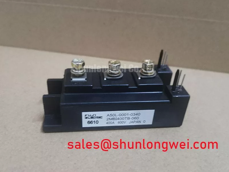
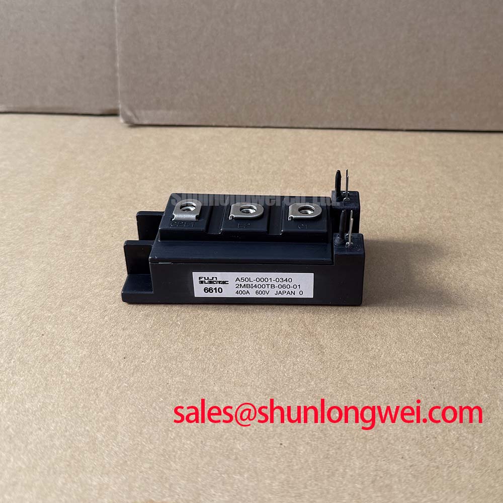
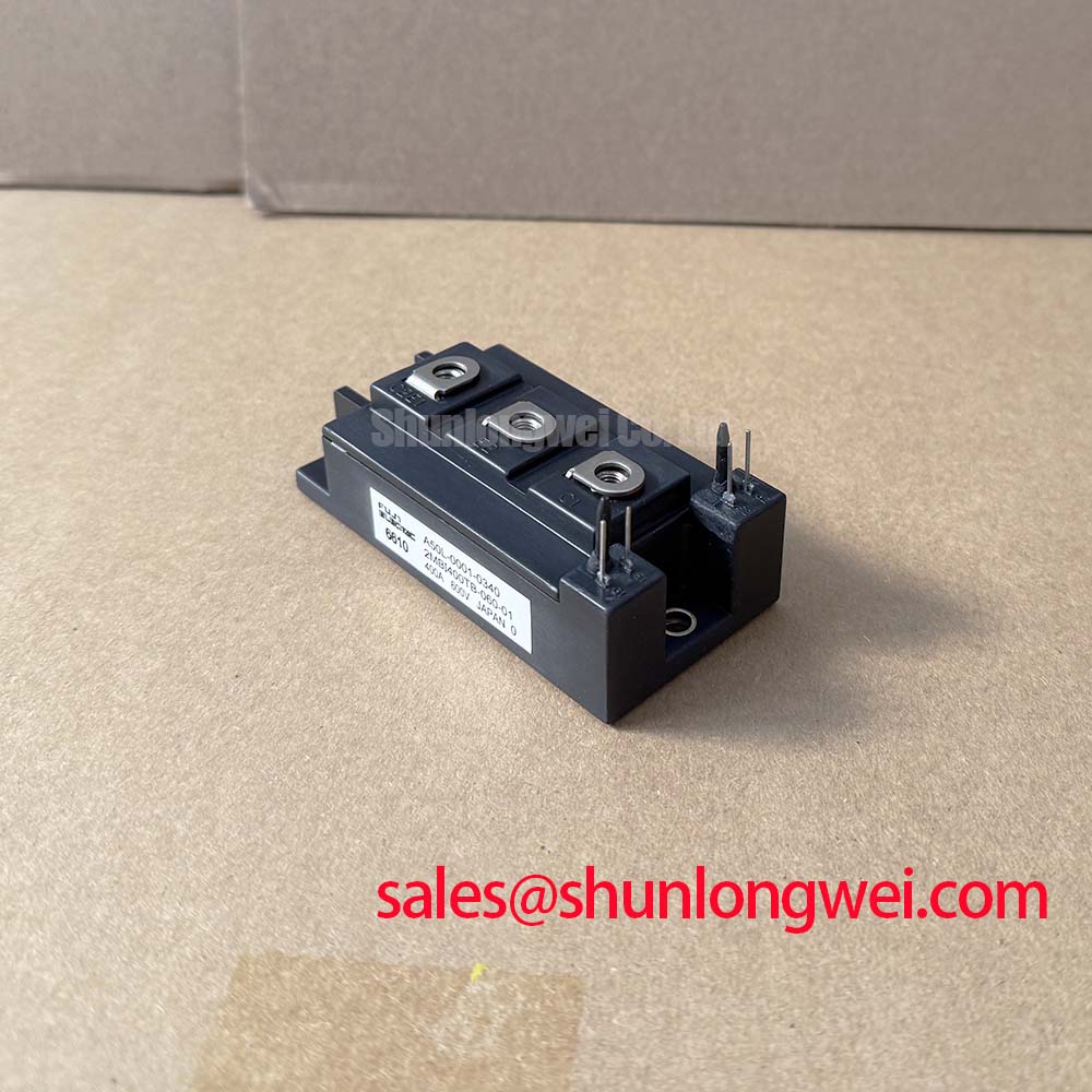
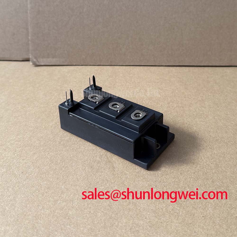
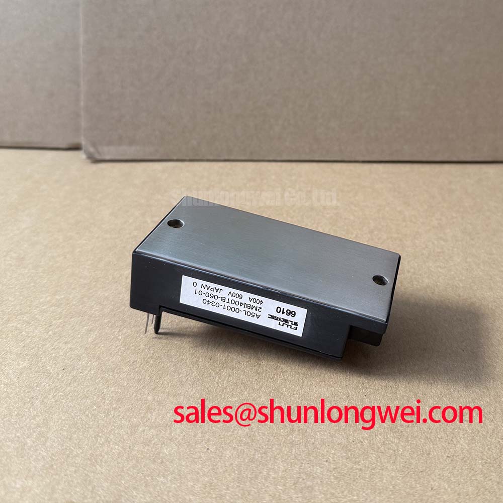
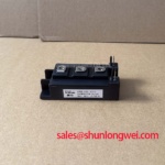
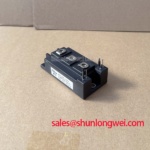
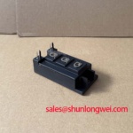
Fuji Electric 2MBI400TB-060-01 Dual IGBT Module
Highlights & Technical Overview
Solving Thermal Limits in High-Current Switching Systems
Designing high-power motor drives and industrial inverter systems often leaves engineers struggling with thermal bottlenecks. As continuous switching currents rise to 400A, even minor increases in internal conduction losses can cause catastrophic thermal runaway. The 2MBI400TB-060-01 IGBT Module from Fuji Electric directly solves this bottleneck by coupling a low collector-emitter saturation voltage (VCE(sat)) of 1.9V with an ultra-low junction-to-case thermal resistance (Rth(j-c)) of 0.10 °C/W.
This module provides thermal margin in high-frequency switching drives by pairing low-loss chips with an optimized dual-pack heat dissipation path. Key technical parameters include: 600V | 400A | Rth(j-c): 0.10 °C/W. Key benefits include: Minimizes heatsink size constraints and prevents localized hotspot degradation. For those decoding IGBT datasheets, standard parallel operations are greatly simplified by this package's positive thermal coefficient.
Frequently Asked Questions
Resolving Critical Field Engineering Queries
What is the exact junction-to-case thermal resistance (Rth(j-c)) of the 2MBI400TB-060-01, and how does it affect heatsink selection?
The module features an Rth(j-c) of 0.10 °C/W for the IGBT and 0.16 °C/W for the free-wheel diode (FWD). This low resistance allows rapid thermal dissipation, enabling engineers to design more compact heatsinks without risking junction temperatures exceeding the safe 150°C operating limit.
Does the 2MBI400TB-060-01 support safe paralleling, and how does its VCE(sat) temperature coefficient behave?
Yes. The silicon chip design exhibits a positive temperature coefficient for VCE(sat) at high current levels. As temperatures increase, the on-state voltage drop rises naturally. This balances the current distribution across parallel modules and prevents localized thermal runaway.
What are the recommended mounting and terminal torque parameters for this dual-pack module?
The ideal mounting torque for both the baseplate to the heatsink and the electrical terminal connections is 3.5 N·m using M5 screws. Maintaining a torque of 2.5 to 3.5 N·m ensures optimal thermal contact while preventing physical stress on the ceramic isolation substrate.
What is the short-circuit withstand capability of this 600V/400A U-series IGBT module?
The module possesses highly robust short-circuit ruggedness, capable of withstand times compliant with typical industrial gate driver protection delays. It can handle peak pulse currents of up to 800A (and withstand higher transients) when paired with desaturation detection circuits.
Key Technical Specifications
Standardized Electrical and Thermal Operating Limits
| Parameter / Symbol | Standard Rating / Value | Engineering Significance |
|---|---|---|
| Collector-Emitter Voltage (VCES) | 600 V | Provides excellent voltage overhead for industrial equipment operating on nominal 200V to 400V AC lines. |
| Continuous Collector Current (IC) | 400 A (at Tc = 25°C) | Specifies the continuous current-carrying capability per switch under active thermal management. |
| Peak Collector Current (ICP) | 800 A (1 ms pulse) | Accommodates transient starting surges common in heavy mechanical machinery. |
| Collector-Emitter Saturation Voltage (VCE(sat)) | 1.9 V (Chip level typ.) / 2.2 V (Terminal typ.) | Directly determines conduction losses to optimize system operating efficiency. |
| IGBT Thermal Resistance (Rth(j-c)) | 0.10 °C/W (max) | Ensures low thermal impedance to prevent silicon overheating. |
| Gate-Emitter Voltage (VGES) | ±20 V | Defines the safe driving voltage thresholds for gate control. |
| Isolation Voltage (Visol) | 2500 V AC (for 1 minute) | Ensures high galvanic isolation between raw high-power terminals and the grounded baseplate. |
Download the 2MBI400TB-060-01 datasheet for detailed specifications and performance curves.
Technical & Design Deep Dive
A Closer Look at Thermal Mechanics and Chip Layout
To fully understand the reliability of the 2MBI400TB-060-01, engineers must look closely at its physical and thermal packaging design. Thermal resistance can be conceptualized as a narrow pipe in a water drainage system. If the pipe is too narrow, water accumulates at the source. By lowering the Rth(j-c) to 0.10 °C/W, the thermal "drainage" is widened, ensuring heat flows efficiently from the silicon to the heatsink. Detailed considerations on thermal path layout can be explored in our technical resource Why Rth Matters: Unlocking IGBT Thermal Performance.
Additionally, the positive temperature coefficient of VCE(sat) acts like an automated highway toll system. When one lane gets congested, cars automatically distribute to other lanes. Similarly, when a module in a parallel system heats up, its saturation voltage rises, shedding excess current to cooler sibling devices. This self-balancing behavior prevents current crowding without requiring complex digital control algorithms. For designers implementing custom gate drive topologies, avoiding common pitfalls is crucial to prevent failure, as detailed in our guide on IGBT Failure Analysis.
What is the primary benefit of the low Rth(j-c) in this module? It prevents thermal runaway by accelerating heat transfer away from the silicon junction.
What operating systems are best suited for this module? High-power industrial systems requiring reliable 600V/400A switching under constant thermal stress.
Application Scenarios & Value
Maximizing System-Level Efficiency in Harsh Industrial Environments
For 400V AC servo drives requiring extreme thermal safety, this 600V module is the optimal choice. When operating under high-load conditions, such as driving heavy-duty AC motor drives, the system must survive severe start-up surges. The robust peak current capability of 800A guarantees the module withstands starting surges without structural fatigue. In addition, its integrated free-wheeling diode provides low reverse recovery energy losses, making it ideal for high-frequency PWM switching stages.
In addition to Variable Frequency Drives (VFDs), this device operates reliably in industrial welding power supplies and high-capacity Uninterruptible Power Supply (UPS) systems. For configurations demanding different physical layouts, sibling modules like the 2MBI400TA-060 or the 2MBI400TC-060-01 offer similar 600V/400A performance in alternative packaging styles. This ensures design continuity when migrating between various mechanical footprints.
Implementing standard protective designs such as an external Short-Circuit Withstand Time buffer is recommended to protect the silicon. As factory automation demands increase, choosing long-lasting components from reputable manufacturers like Fuji Electric remains a strategic choice to minimize total cost of ownership and guarantee high system uptime.