


Content last revised on September 12, 2026
Benchtop Waveform Tuning: Galvanic Gate-Drive Isolation for the 2MBI400TB-060
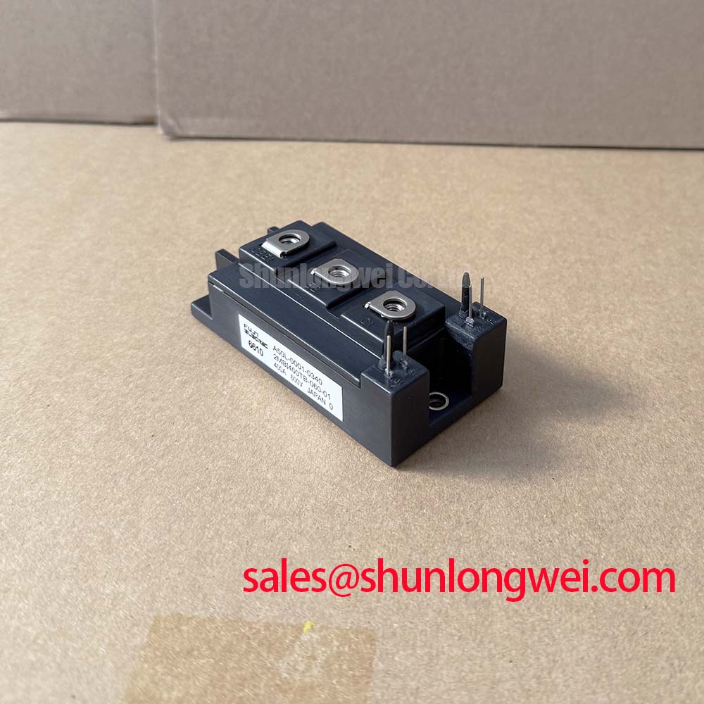
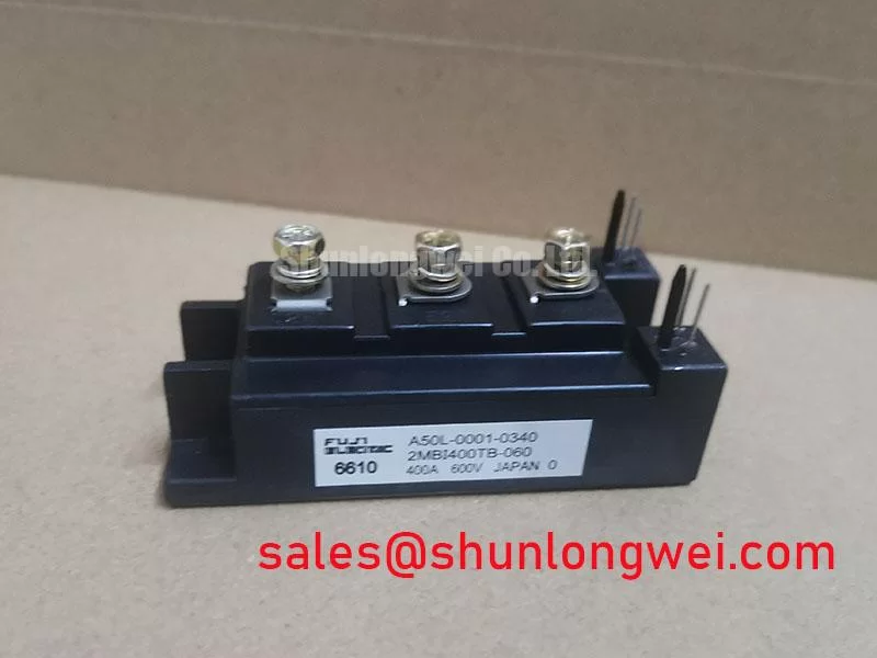
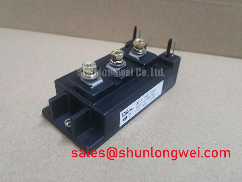
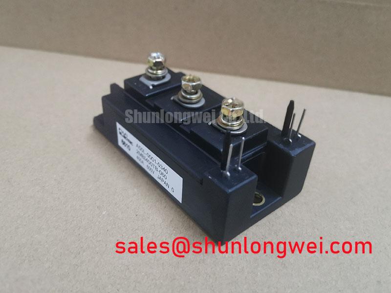
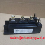
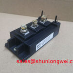
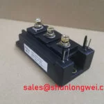
Before energizing a replacement, isolate the 2MBI400TB-060, confirm the collector, emitter, and gate terminal identification against the original assembly documentation, and record a cold-state reference with a calibrated multimeter. A diode-mode check across the appropriate power terminals can help identify an unexpected short or open condition, but the reading must be interpreted against a known-good module and the complete circuit topology. Do not apply gate drive during this incoming inspection.
| Parameter | Official Specification | Engineering Significance |
|---|---|---|
| Collector-emitter voltage, VCES | 600 V | Defines the module’s rated blocking-voltage class for the switching circuit. |
| Continuous collector current, IC | 400 A at Tc = 25°C | Specifies continuous current capability per switch under the stated case-temperature condition. |
| Peak collector current, ICP | 800 A for 1 ms | Provides a short-duration pulse rating for transient current conditions within the specified limits. |
| Collector-emitter saturation voltage | 1.9 V chip-level typical; 2.2 V terminal typical | Used when estimating conduction loss and comparing measured switching-leg behavior. |
| IGBT thermal resistance, Rth(j-c) | 0.10°C/W maximum | Relates junction temperature rise to case temperature during thermal analysis. |
| Gate-emitter voltage, VGES | ±20 V | Defines the stated gate-emitter voltage boundary for the control interface. |
| Isolation voltage, Visol | 2500 V AC for 1 minute | Specifies the dielectric withstand rating between the power section and baseplate isolation system. |
The 2MBI400TB-060 is a high-current Fuji Electric IGBT module with a stated 2500 V AC isolation voltage for one minute. This is an official dielectric withstand specification; it should not be converted into a blanket claim about reinforced insulation, common-mode transient immunity, or system-level safety certification. When a traction inverter or industrial converter uses isolated gate drivers, the system designer should verify the driver’s isolation rating, transient immunity, creepage, clearance, and insulation coordination as a complete assembly. The module itself does not independently establish compliance with railway, EMC, or equipment-level certification requirements.
During bench testing, observe the gate-emitter waveform directly at the module terminals with a measurement setup suitable for the switching environment. A clean command signal at the driver output does not prove that the gate voltage remains clean at the module pins. Gate-loop inductance, return-path coupling, driver supply behavior, and power commutation can all influence the measured waveform. Minimize the physical loop area between the isolated driver output, gate connection, and emitter return, then verify turn-on and turn-off behavior under the actual switching current and DC-link conditions.
The ±20 V VGES rating is an official specification, not a recommended operating waveform. Designers should verify the selected positive and negative gate-drive levels from the applicable Fuji Electric documentation and the gate-driver design. If a suspected false trigger appears, compare the gate-emitter signal with the complementary switch command, DC-link waveform, and emitter-reference movement on the same time base. Anomalous behavior may indicate measurement-loop pickup, common-mode coupling, insufficient driver supply control, or a power-loop transient; it should not be assigned to one cause without corroborating measurements.
For a related system-level comparison, engineers may review the 2MBI400U4H-170 as a separate power-semiconductor product. Its suitability, voltage class, gate-drive requirements, and switching behavior must be evaluated from its own documentation rather than inferred from the 2MBI400TB-060.
💡 Bench Tip: Keep the module and test instruments protected against ESD, discharge the DC link fully before reconnecting any gate or power lead, and compare cold-state terminal behavior with a verified reference module before applying a control signal.
2MBI400TB-060 Thermal-Electrical Optimization: Long Motor Lead Reflected-Wave Voltage Practical Tuning
Long motor cables can behave as transmission-line elements, particularly when switching edges are fast compared with the cable’s electrical propagation time. Impedance mismatch at the motor terminals can produce reflected voltage that raises the stress seen by the inverter output and motor insulation. This is a Design Consideration for the complete drive system, not a characteristic that can be assigned to the IGBT module alone. The system integrator should measure the phase-to-phase and phase-to-ground waveforms at the inverter and motor ends under representative cable length, load, and switching conditions.
The 600 V VCES rating establishes the module’s official collector-emitter voltage class. It does not define an allowable DC-link voltage, switching overshoot, motor-cable length, or filter configuration for every traction inverter. Designers should keep parasitic inductance controlled in the commutation path and verify the measured peak voltage against the application’s DC-link operating range and transient limits. Any output reactor, dv/dt filter, or common-mode network should be selected from system measurements, motor insulation requirements, switching frequency, and thermal losses.
At the same time, conduction loss requires attention to the stated 1.9 V chip-level typical and 2.2 V terminal typical VCE(sat) values. These are typical values rather than a universal worst-case loss guarantee. Actual dissipation depends on collector current, junction temperature, gate conditions, current sharing, switching pattern, and measurement location. A thermal model should combine measured or documented conduction behavior with switching-loss information from the applicable device data, then compare the resulting junction-temperature estimate with the permitted operating conditions.
Where phase-angle control, line-frequency ripple, or regenerative operation is present, inspect the current waveform as well as the voltage waveform. Ripple in the DC link can alter instantaneous switching stress and thermal cycling even when the average current appears acceptable. An RC snubber may reduce a localized ringing component, but its resistor and capacitor losses, pulse capability, layout, and interaction with the main commutation loop require validation on the finished assembly. There is no universal snubber value that can be assigned from the module part number alone.
The 800 A for 1 ms ICP specification is an official pulse-current rating. It should not be treated as permission for repetitive overload or as a substitute for short-circuit protection. When troubleshooting a high-current inverter, capture the gate command, collector-emitter voltage, phase current, and DC-link voltage together. A distorted waveform may result from cable reflection, probe-ground error, driver timing, saturation, or an abnormal load, so the measurement arrangement should be checked before replacing the module.
Cosmic-Ray Robustness and Voltage Derating for the 2MBI400TB-060
Altitude, terrestrial radiation environment, and single-event reliability can be relevant in specialized high-voltage applications, but the supplied official specifications for the 2MBI400TB-060 do not provide a FIT value, SEB qualification result, cosmic-ray test profile, or altitude derating curve. A numerical SEB rate or a fixed DC-bus derating percentage would therefore require an authoritative Fuji Electric reliability source or a recognized qualification document. It should not be inferred from the 600 V VCES rating.
For a high-speed rail or heavy freight locomotive traction-inverter evaluation, treat voltage margin as a system verification task. Record the highest steady-state DC-link voltage, regenerative rise, switching overshoot, and abnormal operating transients at the module terminals. The test plan should also define the relevant altitude, cooling condition, switching pattern, and fault-clearing behavior. If the equipment operates above the conditions covered by the original design documentation, the responsible system engineer should obtain an applicable derating or reliability assessment before approving the module for that duty.
During fault investigation, inspect the gate-emitter waveform and collector-emitter blocking behavior with suitable high-voltage probes after confirming safe discharge procedures. A failed module may show a low-impedance path, but that observation alone does not identify whether the initiating event was overvoltage, overcurrent, thermal stress, gate damage, insulation breakdown, or an external fault. Compare the failed unit with the known-good signal path and examine the protection timing, current sensor response, and fuse or breaker coordination.
Fast semiconductor fuses are commonly evaluated using their documented I2t capability and the prospective fault current of the converter. This is an Engineering Recommendation for system protection analysis, not an official protection rating for this particular module. The integrator should verify that the protection device, gate-driver fault response, desaturation or overcurrent strategy, and mechanical containment are coordinated for the actual DC-link energy. No field failure rate or service-life figure is stated here because such data requires a traceable source and defined test population.
For application background concerning resonant switching behavior and appliance power stages, the technical discussion at Resonant Topologies in Home Appliances may provide useful topology context. It should not be used as a substitute for the Fuji Electric documentation governing the 2MBI400TB-060. Additional semiconductor information is available from Fuji Electric Power Semiconductor and IPM Modules.
Transient Dynamics and Electrical Design: Baseplate Thermal Grease Layer Control on 2MBI400TB-060
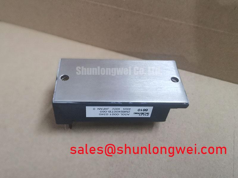
The module’s official 0.10°C/W maximum Rth(j-c) value assumes the thermal path is implemented within the conditions defined by the relevant manufacturer documentation. It does not guarantee the thermal performance of an assembled heatsink. Case flatness, heatsink finish, interface-material behavior, clamping force, contact pressure, and cooling airflow all influence the final junction-to-ambient result. Before installation, clean both mating surfaces with a process compatible with the baseplate and thermal interface material, and inspect for contamination, burrs, or visible damage.
A thin, continuous thermal interface layer is generally a Design Consideration because excessive material can increase thermal resistance while insufficient coverage can leave air voids. The exact compound, application method, acceptable thickness, and coverage pattern should be taken from the module and thermal-interface supplier instructions. Do not assume that a thickness range used for another package or heatsink applies to this module. After mounting, inspect for evidence of uneven contact and confirm that the heatsink remains mechanically stable during thermal cycling.
Mounting hardware should be tightened progressively in a crosswise sequence so that the baseplate is seated without imposing a local bending load. The correct screw size, washer arrangement, torque value, and sequence are assembly-specific Design Considerations and should be verified from the applicable Fuji Electric mechanical drawing. Do not use a generic torque value as an official specification for the 2MBI400TB-060. After installation, recheck electrical isolation with an approved procedure and confirm that the power terminals, gate connections, and heatsink remain free from mechanical strain.
Thermal validation should correlate case-temperature measurements with switching current, duty cycle, ambient condition, and cooling-system state. A brief bench test at low load cannot establish the pulse peak junction-temperature margin for a traction inverter. Designers should use the documented transient thermal impedance information when available, combine it with the measured load profile, and verify the calculated result with appropriately placed temperature instrumentation. If the module is being evaluated against the 2MBI400TB-060-01 listing, confirm the exact ordering information and documentation before treating it as the same procurement target.
Safety Interlock Note: Fully isolate and discharge the converter before disconnecting the gate cable, power terminals, or heatsink assembly.