Content last revised on October 3, 2026
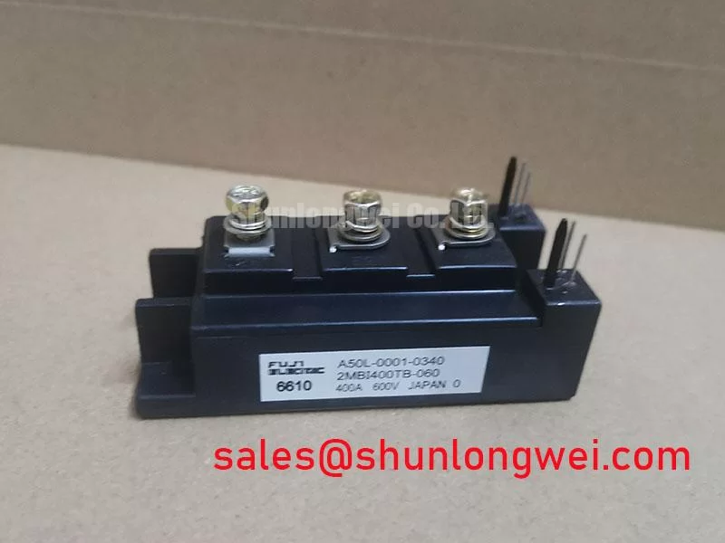
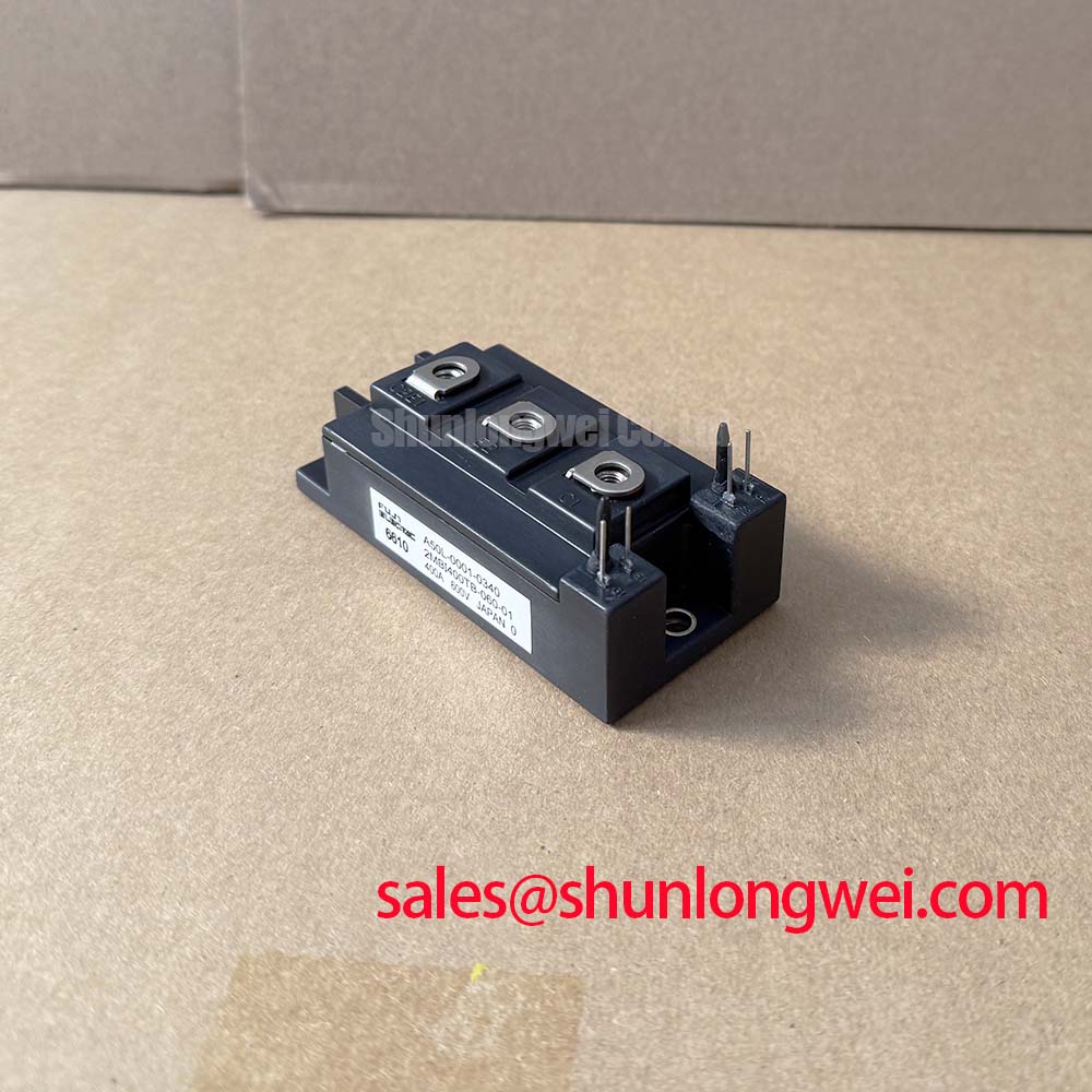
Field Diagnostics and Commissioning: Busbar Symmetry Around the 2MBI400TB-060-02
| Model | 2MBI400TB-060-02 |
|---|---|
| Manufacturer | Fuji Electric |
| Product category and package | IGBT module, Fuji Power Module |
| Rated voltage | 600 V (Official Specification) |
| Rated current | 400 A (Official Specification) |
Measure the cold resistance between each accessible power terminal and the heatsink, then compare collector-to-emitter and gate-to-emitter readings with the disconnected, known-good circuit before energizing the 2MBI400TB-060-02. Isolate the driver and discharge the DC link first. A low reading is a reason to investigate, not proof that the module alone has failed: parallel snubbers, discharge paths, and connected loads can affect an in-circuit meter reading. Record the meter polarity and test configuration so a second technician can repeat the check.
The module carries 600 V and 400 A ratings (Official Specifications). Those ratings establish comparison points for the replacement review; they do not establish a permissible DC-link setting, switching peak, or current-sharing limit for the assembled converter. As a Design Consideration, inspect both the positive and negative busbar paths for comparable length, contact area, and mechanical seating where devices operate in parallel. Unequal path impedance can produce unequal switching transients even when static meter readings appear similar. Check for loose joints, heat discoloration, displaced insulation, and changes to the original busbar stack before attributing a fault to the module.
During controlled commissioning, compare collector-to-emitter voltage and gate-to-emitter voltage waveforms at equivalent positions in each switching path. Keep the probe reference local to the terminal being measured; a remote reference can make common-mode noise look like gate oscillation. Match gate-loop routing and connection integrity when comparing parallel positions, because static sharing and dynamic sharing are different questions. A positive temperature coefficient of on-state voltage can assist static current sharing in some IGBTs, but that behavior must not be assumed for this model without its operating-characteristic curves. The installed driver, interconnects, and measured switching waveforms determine whether the paths are balanced.
When evaluating another part for an existing footprint, treat the 2MBI200J-120 as a separate cross-model comparison, not a drop-in replacement. Confirm its electrical ratings, terminal arrangement, mounting pattern, gate-drive requirements, and protection coordination against the equipment drawings before any substitution decision.
Assembly Integrity and Layout: Reliability Questions Beyond Nameplate Ratings
Inspect the module-to-heatsink joint for uneven seating, trapped debris, and disturbed fasteners where a temperature alarm or intermittent shutdown follows maintenance. Compare the installed assembly with the original mechanical drawing, then examine the surrounding insulation and busbar spacing for movement or contamination. Field Alert: Follow the equipment’s fastening specification and apply thermal interface material evenly rather than tightening a suspect joint by feel.
As a Design Consideration, thermal assessment should reflect the actual switching and braking duty, cooling path, and ambient conditions. A short current pulse can raise junction temperature before the heatsink sensor responds. Transient thermal impedance data, if available for the exact module, can support that assessment; the 400 A rating alone cannot establish pulse temperature margin. Check the fault log against load events and cooling performance, and have the system engineer validate junction-temperature estimates against the module documentation used for that installation.
High-altitude service raises a separate reliability question. As a Design Consideration, changes in atmospheric neutron exposure and operating voltage may affect single-event burnout risk in power semiconductors. No FIT figure, altitude derating curve, or single-event burnout limit is established here for the 2MBI400TB-060-02; do not turn its 600 V rating into a failure-rate prediction. For equipment operated at altitude, request application-specific reliability evidence and assess DC-link headroom against measured steady-state voltage and switching peaks. A high-speed rail or heavy freight locomotive traction inverter is a possible compatibility study, not an established application approval for this module.
If the high-side driver uses a bootstrap supply, examine its voltage during the longest commanded on-time and immediately after switching. As an Engineering Recommendation, size and verify that supply using the driver’s charge demand, quiescent consumption, leakage, operating sequence, and measured voltage droop. Do not infer bootstrap capacitance or gate charge from the module’s voltage and current ratings. Fuji Electric’s high-speed discrete IGBT information describes a different product category and should not be used as a specification for this module.
2MBI400TB-060-02 Protection: Investigating Gate Bounce and Cross-Conduction
Capture gate-to-emitter voltage on the device that should be off while the opposite switch turns on. A rising off-state gate waveform may indicate coupling through the driver path, shared emitter impedance, or probe setup; correlate it with collector-to-emitter voltage, DC-link current, and the driver fault record before deciding that cross-conduction occurred. Repeat the measurement with the shortest practical probe loop and compare it with a known-good phase under the same test conditions.
As a Design Consideration, keep the gate return close to its outgoing path and minimize inductance in the commutation loop to limit ringing and turn-off overshoot. A low-impedance off-state path or an active Miller clamp can be evaluated if measured gate bounce threatens the installed driver’s off-state margin. Negative off-state bias is another driver-level option, but its value and compatibility must come from the module and driver specifications and be verified on the assembled converter. Neither feature should be presumed necessary or present in the 2MBI400TB-060-02.
Check the snubber, DC-link capacitors, and any MOV network as a coordinated protection system. An MOV does not replace tight local commutation paths; its location and response must be assessed against the actual transient it is intended to absorb. Compare measured collector-to-emitter peaks with the module’s 600 V rating (Official Specification), accounting for the equipment’s DC-link voltage and test conditions. The system designer determines the acceptable operating margin. For broader switching-loss and drive-layout context, Unlocking Efficiency in Industrial Drives is background reading, not evidence that this Fuji Electric module uses the technology discussed there.
If a drawing shows a nearby SKM100GB063D, identify its actual circuit position from that drawing before interpreting a shared DC-link fault. Its presence does not establish that it is the rectifier or a direct companion to this module. Fuji Electric’s RC-IGBT module information likewise covers a distinct module family and cannot establish the internal topology of the 2MBI400TB-060-02.
2MBI400TB-060-02 Circuit Protection: Checking Dynamic Braking Events
Trace a braking-related DC-link overvoltage trip through the brake command, chopper gate signal, resistor path, and measured link-voltage waveform. A trip during deceleration does not by itself identify a failed 2MBI400TB-060-02: regeneration, an open resistor circuit, chopper control, and voltage sensing all warrant checks. Use the equipment schematic to determine whether the braking switch is external to this module; no internal braking IGBT is specified by the core product data.
As an Engineering Recommendation, assess the braking resistor and switch against the machine’s deceleration energy, repetition rate, cooling, and measured DC-link response. Inspect resistor terminations and thermal protection for evidence of interruption, then compare the chopper’s commanded state with its observed switching behavior. Keep the braking current path and its measurement reference clear in the troubleshooting record so a gate-drive fault is not confused with a missing power path.
After repairs, increase operating demand under the equipment’s commissioning procedure while recording DC-link peaks, switch waveforms, and heatsink temperature. Stop if the measured behavior approaches the limits established for the complete converter. Release the machine only after the observed braking response agrees with its original control and protection design.