Content last revised on September 10, 2026
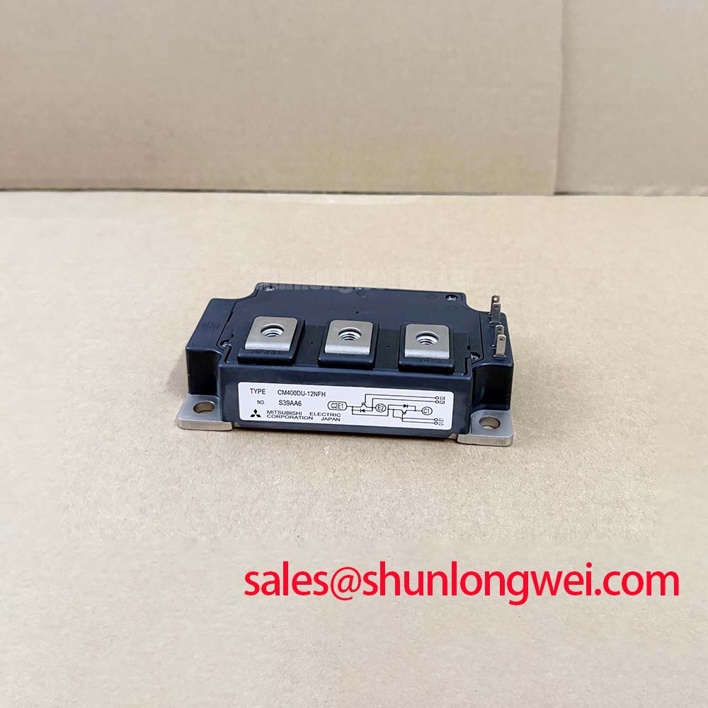
Mitsubishi CM400DU-12H: High-Power 600V 400A Dual IGBT Module for Industrial Systems
The Mitsubishi CM400DU-12H is a dual IGBT Module optimized for high-power switching applications. Utilizing a half-bridge configuration, it provides a robust power stage for medium-voltage industrial converters. This device features a collector-emitter voltage (Vces) of 600V and a continuous collector current (Ic) of 400A, supported by a total power dissipation (Pc) of 1130W. It features low conduction losses and an isolated copper baseplate to simplify system assembly. For 600V industrial inverter systems prioritizing thermal margin and low conduction loss, this 400A half-bridge module is the optimal choice.
Key Parameter Overview
Decoding the Specs for Enhanced Thermal Reliability
The operating parameters of the CM400DU-12H dictate its efficiency and safety limits. Below is a detailed view of its primary technical specifications:
| Parameter Description | Symbol | Rated Value / Spec |
|---|---|---|
| Collector-Emitter Voltage (G-E Short) | Vces | 600V |
| Continuous Collector Current (Tc = 25°C) | Ic | 400A |
| Peak Collector Current (Pulse) | Icm | 800A |
| Continuous Emitter Current (Free-Wheel Diode) | Ie | 400A |
| Collector-Emitter Saturation Voltage (Tj = 25°C) | Vce(sat) | 2.4V (Typical) / 3.0V (Max) |
| Isolation Voltage (Main Terminal to Baseplate, AC 1 min) | Viso | 2500Vrms |
| Maximum Collector Dissipation (Tc = 25°C) | Pc | 1130W |
| Junction Operating Temperature Range | Tj | -40°C to +150°C |
Download the CM400DU-12H datasheet for detailed specifications and performance curves.
Application Scenarios & Value
Achieving System-Level Benefits in High-Power Motor Drives
Engineers designing high-power motor control systems face severe transient stress during start-up. Motor acceleration demands high inrush currents, risking overcurrent faults or thermal breakdown. The CM400DU-12H handles this by supporting peak emitter currents (Iem) and peak collector currents (Icm) up to 800A. This surge capacity prevents damage during heavy-duty motor starts in conveyor belts or CNC machines. It is used in Variable Frequency Drives (VFDs), industrial servo drives, and uninterruptible power supplies (UPS).
When implementing these modules in industrial facilities, engineers must ensure compliance with electromagnetic compatibility and safety regulations, such as the IEC 61800-3 standard. By integrating the half-bridge circuit directly into the power stage, designers minimize stray inductance. To help with hardware design, engineers can refer to the ultimate guide to IGBT modules for selecting optimal layouts.
For systems requiring less current, the CM300DU-12H offers a collector current of 300A, while systems needing higher power density can utilize the CM800DU-12H with an 800A rating.
Technical & Design Deep Dive
A Closer Look at the Isolated Baseplate and Low Saturation Loss
The thermal design of high-power modules dictates system longevity. The CM400DU-12H utilizes an isolated copper baseplate. What is the primary benefit of its isolated baseplate? It simplifies thermal management by isolating components from the heatsink. Think of the isolated copper baseplate as an electrical firewall. Just as a digital firewall blocks external threats while letting authorized data pass, this physical barrier prevents high-voltage leaks to the chassis while allowing thermal energy to flow to the heatsink. This layout eliminates external insulation pads, lowering thermal resistance and maximizing the 1130W power dissipation limit.
Efficiency is further enhanced by the low collector-emitter saturation voltage (Vce(sat)) of 2.4V. This specification minimizes on-state conduction losses during peak load operations. Furthermore, as the junction temperature rises, the saturation voltage increases to 2.6V at 125°C. What ensures balanced current in parallel setups? The positive temperature coefficient of collector-emitter saturation voltage enables natural current sharing. This dynamic behavior prevents thermal runaway in parallel configurations without requiring complex driver monitoring. Designers can learn more about configuring gate signals and protecting against transient overvoltage by referencing the guide on decoding IGBT datasheets.
Frequently Asked Questions
Addressing Common Design and Testing Inquiries
How does the positive temperature coefficient of the CM400DU-12H benefit parallel operations?
The positive temperature coefficient causes the collector-emitter saturation voltage (Vce(sat)) to rise from 2.4V at 25°C to 2.6V at 125°C. When modules are connected in parallel, the device carrying more current heats up, increasing its resistance and shifting current to the cooler module. This natural self-balancing mechanism prevents localized overheating and thermal runaway.
What is the significance of the 2500V isolation voltage rating?
The isolation voltage (Viso) rating of 2500Vrms (measured for 1 minute at AC) means the internal electrical components are isolated from the metal baseplate. This allows multiple modules to be mounted directly onto a single shared heatsink without the risk of high-voltage leakage, simplifying system packaging and reducing overall assembly costs.
How should the CM400DU-12H be tested using a multimeter to confirm functionality?
To perform a basic check, configure your multimeter to diode mode. Measure the forward voltage of the free-wheel diode between the emitter and collector terminals. To check for gate-to-emitter shorts, measure the resistance between the gate and emitter terminals; it should read as an open circuit. For a comprehensive, step-by-step diagnostic process, refer to the tutorial on testing an IGBT module with a multimeter.
Adopting highly isolated switching modules serves as a strategic cornerstone for industrial systems aiming to align with global energy-efficiency regulations.