Content last revised on October 3, 2026
Assembly Integrity & Layout Architecture: Implementing Desaturation Detection for CM400DY-12
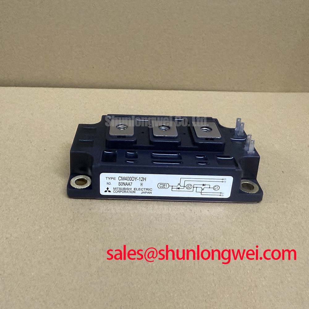
Before fitting the replacement, isolate the power stage, inspect the module body and terminals, then record the cold-state diode-check readings against the known-good phase leg and verify the nameplate boundary of 600 V and 400 A. These checks help separate installation faults from gate-drive or external circuit problems without applying uncontrolled DC-link energy.
| Parameter | Official Specification |
|---|---|
| Manufacturer | Mitsubishi Electric |
| Part number | CM400DY-12 |
| Product category | IGBT Module |
| Rated voltage | 600.0 V |
| Rated current | 400.0 A |
| Package | Module |
The published product information identifies the CM400DY-12 as a Mitsubishi Electric module with a 600.0 V voltage rating, a 400.0 A current rating, and a module package. These are Official Specification values for product identification. Switching frequency, gate threshold, short-circuit withstand time, gate charge, thermal resistance, isolation voltage, terminal arrangement, and NTC details should be confirmed from the applicable manufacturer documentation before a service replacement is approved.
During incoming inspection, confirm the terminal markings from the original equipment documentation before connecting the gate driver. A diode-mode check can be useful for comparing the freewheel diode paths between phases, but the reading is a cold-state diagnostic reference rather than a guaranteed acceptance value for this model. Keep the gate terminals isolated from the power terminals during resistance checks, and discharge any driver supply capacitors before handling the assembly.
For a utility-scale centralized battery energy storage PCS, the protection circuit should monitor the collector-emitter condition during commanded turn-on and distinguish a legitimate high-current transient from a sustained short-circuit event. Type I protection generally refers to a fault occurring during turn-on, while Type II protection concerns a fault developing after the device has already entered conduction. The desaturation threshold, blanking interval, fault latch behavior, and soft turn-off sequence are properties of the complete gate-driver design, not published ratings of the CM400DY-12.
An Engineering Recommendation is to use a two-stage fault response when the driver and system protection study support it. The first stage can reduce gate current to limit di/dt, while the second stage completes turn-off under controlled conditions. Any target such as a sub-10 microsecond response must be validated against the actual driver propagation delay, current-sense network, module short-circuit capability, DC-link voltage, stray inductance, and oscilloscope capture. It must not be treated as an official CM400DY-12 limit without the relevant Mitsubishi Electric documentation.
Keep the desaturation sensing path physically separate from the high-current commutation path. Minimize the loop area around the gate driver, gate resistor, and emitter return, and route the fault-sense return so that power-current voltage drop does not appear as a false protection signal. Clearance and creepage around the DC-link and phase terminals should follow the applicable working-voltage, pollution-degree, altitude, and enclosure requirements determined by the system engineer.
For background on power semiconductor module technologies and manufacturer documentation, consult Mitsubishi Electric Power Semiconductors & High-Power Modules. In a PCS with regenerative operation, the braking chopper and resistor bank also require independent verification of pulse energy, thermal recovery, and fault isolation. The module rating alone does not establish the safe operating envelope of that complete branch.
Field Diagnostics & Commissioning: Negative Gate Bias vs Active Miller Clamping in CM400DY-12 Topologies
High dv/dt at one switching position can couple through the opposing device gate circuit and create an unintended turn-on command. When commissioning the CM400DY-12, monitor gate-to-emitter voltage at the module terminals, not only at the driver output board. Compare the command signal, gate waveform, collector-emitter waveform, and fault line during both no-load and controlled-current tests. A waveform that appears clean at the driver board can change after cable inductance, connector resistance, and the module power loop are included.
Negative gate bias is used in some IGBT gate-drive architectures to increase immunity to Miller-induced turn-on. The exact negative voltage is a Design Consideration determined by the selected driver, isolation arrangement, gate-emitter rating, turn-off transient, and the manufacturer’s permitted gate-voltage limits. Do not apply a negative bias range by assumption. The system integrator should verify the required positive and negative gate supplies from the original drive documentation and confirm the measured waveform at the module pins.
An active Miller clamp can provide a low-impedance path that holds the gate near the intended off-state during the opposing device’s high-voltage transition. Its effectiveness depends on clamp placement, driver current capability, common-emitter inductance, propagation delay, and the actual dv/dt of the power stage. If cross-conduction is suspected, inspect the gate waveform for a temporary positive excursion and compare it with the current waveform. This observation may indicate coupling or impedance imbalance, but it does not identify one single failed component without further measurement.
High-side driver power integrity also needs an explicit energy audit. Bootstrap capacitor selection should account for the total gate charge demanded by the switching device, driver quiescent current, leakage, bootstrap diode behavior, operating duty cycle, temperature, and allowable supply ripple. The required capacitance is therefore a system calculation based on the driver data and switching pattern, not a fixed value that can be assigned from the CM400DY-12 part number alone. Where the topology cannot maintain bootstrap refresh, an isolated bias supply may require evaluation.
💡 Bench Tip: Use an ESD-controlled bench and compare every cold-state measurement with a known-good phase leg before applying the DC link or inserting the gate-drive connector.
Preventing Spurious Faults: Derating Guidelines and Mismatched Parameter Guidelines for CM400DY-12
The 600.0 V rating and 400.0 A rating define important product identification boundaries, but they do not represent a universal operating point for every PCS installation. Actual allowable current depends on switching loss, conduction loss, case temperature, cooling interface, switching conditions, duty cycle, fault coordination, and the thermal design of the cabinet. Designers should verify peak voltage and current margins during switching tests rather than infer them from the headline ratings.
Parallel current sharing requires attention to both static and dynamic behavior. IGBT conduction voltage commonly changes with temperature, and a positive temperature relationship can support static sharing under suitable matched conditions. Dynamic sharing remains sensitive to gate-loop impedance, driver timing, emitter inductance, busbar geometry, and layout symmetry. Modules placed in parallel should therefore use matched physical paths and independently verified gate-drive behavior; the CM400DY-12 product designation alone does not guarantee balanced current distribution.
When a PCS includes a regenerative braking chopper or a high-power braking resistor, evaluate the resistor’s absorbed energy, pulse duration, cooling path, switching repetition, and protective coordination separately from the IGBT module. A resistor bank that is adequate for average dissipation may still impose excessive transient stress during a fault or rapid battery power reversal. Capture the DC-link waveform during controlled commissioning and check the turn-off overshoot against the complete system insulation and semiconductor limits.
Long motor cables or remote inverter loads can produce transmission-line reflections and voltage peaks at the load and, depending on the circuit, at the switching terminals. Although a centralized battery energy storage PCS may use a different output arrangement, the same measurement principle applies wherever long conductors connect to a fast switching bridge. Cable impedance, termination, filter topology, switching edge rate, and physical routing should be evaluated together. If a measured peak approaches the system boundary, the solution may involve a revised filter or gate-drive profile, subject to validation rather than a fixed component prescription.
Thermal interface work deserves the same discipline as electrical commissioning. Clean both mating surfaces, apply the selected TIM according to its manufacturer’s process guidance, and tighten the clamping hardware in a controlled cross-pattern. The correct pressure depends on the module base, heatsink flatness, fastener arrangement, spring hardware, and the mechanical specification of the assembly. Do not substitute a generic torque value for the original equipment manufacturer’s clamping instruction.
For systems using an integrated temperature-sensing element, confirm its presence, resistance curve, and connection from the original module documentation. A generic NTC explanation is available through NTC thermistors, but that reference should not be used to assume a particular sensor is fitted inside the CM400DY-12.
CM400DY-12 Operational Boundaries: Evaluating Gate Drive Loop Geometry to Prevent Limits
Separate the auxiliary gate-drive return from the main high-current emitter route wherever the module and driver architecture provide the corresponding terminals. The purpose is to prevent load-current voltage drop from being added to the gate reference. If the module terminal arrangement does not provide an independent auxiliary return, the integrator should follow the original equipment layout and verify the resulting common-emitter voltage during switching.
Gate-loop parasitic inductance can create ringing during turn-on and turn-off. Reduce the physical loop area, place the gate resistor where the switching-current path is controlled, and avoid routing the gate signal beside high-current commutation conductors for long distances. A damping component may be evaluated as a Typical Starting Point during bench tuning, but its final value must be selected from measured gate waveform, switching loss, fault response, and driver stability.
Use a differential voltage probe and a suitable current probe when checking turn-off overshoot. The peak should be assessed against the DC-link condition, stray-inductance contribution, switching speed, and device voltage boundary. If ringing changes when the probe ground or cable position changes, the measurement setup may be influencing the result; repeat the test with a verified probing arrangement before changing the power circuit.
Thermal and mechanical verification should continue after electrical tuning. The module base must sit evenly against the heatsink, and the clamping sequence should maintain the specified pressure across the contact area. For assemblies using double-sided cooling or pressure clamping, review the mechanical stack-up and thermal path in The Advanced Thermal Management Revolution. For a field replacement assessment, the CM100DY-12E may be reviewed as a related Mitsubishi Electric module, but voltage, current, terminal compatibility, gate-drive requirements, thermal behavior, and mechanical fit must be checked independently before any substitution decision.
After installation, verify gate polarity, phase sequence, insulation condition, driver dead-time behavior, fault reset logic, and DC-link precharge operation at reduced system energy where the equipment permits it. Increase operating stress only after measured waveforms remain within the documented system limits under the intended load and cooling conditions.