Content last revised on September 10, 2026
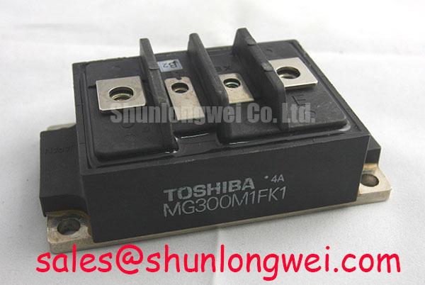
TOSHIBA MG400Q1US65H IGBT Module
Optimized for high-power switching applications, the Toshiba MG400Q1US65H provides unmatched reliability through its industry-leading thermal dissipation path.
Key specifications: 1200V | 400A | Rth(j-c) 0.047 °C/W.
Key benefits: Minimizes thermal stress; accelerates switching transients.
Is the MG400Q1US65H suitable for high-frequency industrial welding? Yes, its typical fall time of 0.05 µs ensures minimal switching losses at elevated frequencies. For high-power inverter designs requiring maximum thermal dissipation at 1200V, this 400A module is the optimal choice.
Application Scenarios & Value
Achieving System-Level Benefits in High-Frequency Power Conversion
Engineers often face severe thermal management challenges when designing heavy-duty industrial systems [5.5]. In high-power applications, such as a Variable Frequency Drive (VFD) or a large-scale Solar Inverter, handling surge currents during startup can cause rapid junction temperature spikes. The MG400Q1US65H addresses this with a massive collector power dissipation of 2650W. This rating ensures the module absorbs transient energy surges without risking thermal runaway. Proper thermal management must be planned to handle this dissipation effectively.
In industrial motor control, maintaining safe operating boundaries is critical. The robust 1200V collector-emitter voltage rating and 400A continuous current capacity provide a generous safety margin within the module's Safe Operating Area. This margin is essential for handling the inductive kickbacks and voltage spikes typical in motor winding isolation. For applications requiring dual-switch configurations within a similar footprint, the MG400Q2YS60A offers a half-bridge topology, whereas systems needing higher current capacity can utilize the MG500Q1US1.
Technical & Design Deep Dive
A Closer Look at the Low Thermal Resistance Design for Long-Term Reliability
At the heart of the MG400Q1US65H performance is its packaging and internal design. The transistor stage features an exceptionally low Thermal Resistance of 0.047 °C/W. This acts like a wide, multi-lane highway for heat. Just as a wide highway prevents traffic congestion during rush hour, a low thermal resistance allows heat generated at the silicon junction to rush out to the heatsink without building up dangerous temperature bottlenecks. This thermal efficiency is crucial for preventing thermal fatigue.
Another critical spec is the input capacitance (Cies) of 34000 pF. This parameter represents a heavy spring on a valve. Just as a heavy spring requires a strong, quick pull to open the valve instantly, the high input capacitance of 34000 pF demands a robust, low-impedance gate driver to inject charge rapidly. This design choice maintains crisp switching edges and prevents the module from lingering in its linear region. Achieving this prevents excessive switching losses during turn-on and turn-off phases.
To protect the system from noise and common-mode transients, the module features an isolation voltage of 2500V AC for one minute. This physical isolation safeguards sensitive control circuitry from high-voltage power paths, making it easier to comply with electromagnetic compatibility standards such as IEC 61800-3. To prevent catastrophic events caused by overcurrent or voltage spikes, designing a reliable gate drive and applying proper IGBT failure analysis methodologies is essential. This is particularly true for high-power single-switch IGBT modules that operate under harsh industrial environments.
What is the primary benefit of its low thermal resistance? It prevents junction overheating during transient overloads by accelerating heat transfer to the heatsink. How does the low switching delay affect system performance? It minimizes switching losses, allowing higher operating frequencies without exceeding thermal limits.
Key Parameter Overview
Essential Electrical and Thermal Specifications
| Maximum Ratings (Ta = 25°C) | ||
|---|---|---|
| Parameter | Symbol | Value |
| Collector-Emitter Voltage | VCES | 1200 V |
| Gate-Emitter Voltage | VGES | ±20 V |
| Continuous Collector Current (DC) | IC | 400 A |
| Pulsed Collector Current (1 ms) | ICP | 800 A |
| Collector Power Dissipation (Tc = 25°C) | PC | 2650 W |
| Electrical Characteristics (Ta = 25°C) | ||
| Collector-Emitter Saturation Voltage (Tc=25°C) | VCE(sat) | 3.0 V (Typ) / 4.0 V (Max) |
| Collector-Emitter Saturation Voltage (Tc=125°C) | VCE(sat) | 3.6 V (Typ) |
| Input Capacitance | Cies | 34000 pF (Typ) |
| Turn-off Time (Inductive Load) | toff | 0.60 µs (Typ) |
| Fall Time (Inductive Load) | tf | 0.05 µs (Typ) / 0.15 µs (Max) |
| Diode Forward Voltage (IF = 400A) | VF | 2.4 V (Typ) / 3.5 V (Max) |
| Thermal & Mechanical Characteristics | ||
| Thermal Resistance (Transistor Stage) | Rth(j-c) | 0.047 °C/W (Max) |
| Thermal Resistance (Diode Stage) | Rth(j-c) | 0.1 °C/W (Max) |
| Isolation Voltage (AC, 1 minute) | VIsol | 2500 V |
Download the MG400Q1US65H datasheet for detailed specifications and performance curves.
Frequently Asked Questions
Addressing Common Engineering Queries and Layout Concerns
How does the Rth(j-c) of 0.047 °C/W directly impact heatsink selection and overall system power density?
A thermal resistance of 0.047 °C/W allows the module to dissipate heat efficiently, reducing the temperature differential between the junction and case. This permits engineers to specify smaller heatsinks or run the module at higher continuous power ratings, directly increasing system power density while maintaining reliability.
What gate drive considerations are necessary to safely manage the 34000 pF input capacitance of this module?
The high input capacitance requires a gate driver capable of delivering high peak currents to quickly charge and discharge the gate. Implementing a proper turn-off gate resistance and ensuring a short physical connection minimizes parasitic inductance and prevents gate oscillation during switching.