
Shunlongwei Co. ltd.
IGBT Module / LCD Display Distributor
Customer Service
+86-755-8273 2562
IGBT Module / LCD Display Distributor
“Radio Frequency of Identificatio (RFID) is a non-contact automatic identification technology using radio frequency technology. Supply chain management, production management and control, anti-counterfeiting and security control, traffic management and control and other fields have great application potential. At present, the working frequency bands of radio frequency identification technology include low frequency, high frequency, ultra-high frequency and microwave band, among which high frequency and ultra-high frequency are the most widely used.
“
Radio Frequency of Identificatio (RFID) is a non-contact automatic identification technology using radio frequency technology. Supply chain management, production management and control, anti-counterfeiting and security control, traffic management and control and other fields have great application potential. At present, the working frequency bands of radio frequency identification technology include low frequency, high frequency, ultra-high frequency and microwave band, among which high frequency and ultra-high frequency are the most widely used.
The RFID system is mainly composed of a reader/writer (target), a transponder (RFID tag) and a background computer. Among them, the reader/writer realizes the data reading, writing and storage of the tag, and is composed of a control unit, a high-frequency communication module and an antenna. It is mainly composed of an integrated circuit chip and an external antenna. The circuit chip usually includes circuits such as radio frequency front-end, logic control, and memory. Tags can be divided into active (acTIve) tags, semi-active (semiacTIve) tags and passive (passive) tags according to the power supply principle. Passive tags are favored because of their low cost and small size.
The basic working principle of the RFID system is: after the tag enters the reader to emit the radio frequency field, the induced current obtained by the antenna is used as the power supply of the chip after the booster circuit, and the induced current with information is converted into a digital signal through the radio frequency front-end circuit. The information that needs to be replied is sent from the tag memory, sent back to the RF front-end circuit through the logic control circuit, and finally sent back to the reader through the antenna.
The goal of the antenna is to transmit the maximum energy in and out of the tag chip, which requires careful design of the antenna and free space and the matching of the tag chip to which it is connected. When the operating frequency is increased to the microwave region, the matching problem between the antenna and the tag chip changes. more severe. For a long time, the development of the tag antenna is based on the input impedance of 50 or 75 ohms. In RFID applications, the input impedance of the chip may be any value, and it is difficult to accurately test in the working state. The lack of accurate parameters, the design of the antenna Difficult to achieve the best.
In recent years, the application of RFID technology has become more and more widely, and it has also received much attention. Especially the RFID system in the UHF frequency band has received more attention due to its long transmission distance and high transmission rate. A typical RFID system consists of an RFID reader and a tag. The RFID passive tag relies on the electromagnetic signal emitted by the RFID reader to supply power, and modulates the electromagnetic signal through reflection to communicate with the reader. Therefore, the quality of the RFID tag antenna design has a key impact on its system performance.
Common RFID reader antennas include folded dipole antennas, fractal antennas, microstrip antennas and axial-mode helical antennas. Since the folded vibrator antenna and the fractal antenna are generally linearly polarized antennas, it is difficult to meet the reader’s identification requirements for Electronic tags in all directions, so it is not suitable for many occasions; while the microstrip antenna is too large due to its size, in miniaturized The use of the reader handset is limited; the axial mode helical antenna is also limited in practical use due to the high axial height. Therefore, how to design a small-sized, low-profile, high-performance circularly polarized RFID antenna has become the focus of attention. (How to make a shortwave antenna)
Four-armed helical antennas are widely used in GPS field due to their excellent circular polarization performance. After further development, Wang-lk Son et al. applied the four-armed helical antenna to RFID, and replaced the traditional monopole antenna with a flat inverted-F antenna as the antenna arm of the four-armed helical antenna, as shown in Figure 1, to achieve good effect. In this paper, an RFID reader antenna with more advantages in size and performance is designed by using this method.

Figure 1. Inverted-F folded four-armed helical antenna
1. Design of Miniaturized Quadruple Helix Antenna
1.1. Design of four-armed helical antenna
The structure of the inverted-F four-armed helical antenna designed in this paper is shown in Figure 2. The antenna consists of 4 identical inverted-F antennas, the horizontal part is printed on a rectangular microwave composite dielectric board with a dielectric constant of 9.6, a size of 60 mm × 60 mm, and a thickness of 1 mm, and the vertical part is printed on the same 4 small FR4 dielectric plates with a thickness of 1 mm. The four antenna feeds are equal-amplitude feeds, and the phases are delayed by 90° counterclockwise in turn to form right-hand circular polarization.
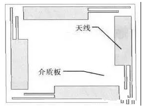
Figure 2. Schematic diagram of the structure of the inverted-F four-armed helical antenna
Since the four arms of the helical antenna are close to each other, the distance between the two opposite arms is about 0.18 λ, and the coupling between the four arms of the antenna is strong. Therefore, when four separate ports are matched, each port cannot be matched individually according to the traditional method, and the power division network is added, and the coupling between the four arms should be fully considered. Simulation with Ansys HFSS shows that the coupling between arms in opposite positions is much larger than that between adjacent arms, as shown in Figure 3. It is because the currents on the opposite arms are parallel to each other, so the mutual influence is too large, while most of the currents on the adjacent arms are perpendicular to each other, and the influence is small, so only the coupling between the opposite arms is considered within a certain range. Assuming that the four antenna arm ports are port 1, port 2, port 3 and port 4 in a counterclockwise direction, the reflection coefficients are Γ11, Γ22, Γ33 and Γ44 respectively, and the coupling coefficients between the opposite antenna arms are M13 and M24. Symmetry between the two pairs of arms, so just analyze the relationship between antenna arms 1 and 3. Assuming that the phase at port 1 is 0, the phase difference generated by the energy transfer from port 1 to port 3 is θ, and the feed phases of port 1 and port 3 are 180° out of phase, then the energy coupled from port 1 to port 3 is in the antenna The phase generated at the port of arm 3 is -180°-θ. Since the antenna spacing is small and θ is small, it can be considered that the phase of the energy coupled from port 1 to port 3 at port 3 is -180°. The feed phase of port 3 is -180°, so the phase of its reflected energy is 180°. Looking at port 3, the energy sent from the port includes the energy reflected by port 3 and the energy coupled by port 1. It has been obtained above that the phases of the reflected energy and the coupled energy at port 3 are 180° and -180°, respectively, so When the reflected energy and the coupled energy are equal in magnitude, their equal amplitudes and opposite phases cancel each other out to achieve the best matching effect, that is, Γ33=M13. On the contrary, when Γ11=M13 is satisfied, the best matching is achieved at port 1. Similarly, port 2 and port 4 can be analyzed.

Figure 3. S-parameter simulation results of the antenna
1.2. Design of feeder network
Generally, there are two feeding methods for the four-armed helical antenna, self-phase-shift feeding and power division network feeding. Since the phase of the self-phase shift is not easy to control, and the structure of the four antenna arms is different, the pattern also changes slightly, so the power division network is selected to realize the feeding. The Wilkinson-style splitter is larger in size and the isolation resistance increases losses, so a simple T-type splitter is used here. Figure 4 is a structural diagram of a power division network.

Figure 4. T-type power division structure diagram
2. Simulation and measurement results of the antenna
Figure 5 shows the comparison of the simulated and measured standing wave results. It can be seen from the figure that the simulated and measured results are in good agreement, and the antenna is in domestic UHF. The measured standing wave in the frequency band 920-925 MHz is below 1.2, and the standing wave in 908-928 MHz is below 1.5, which can meet the practical application. Figure 6 shows the variation of antenna gain and axial ratio with frequency. It can be seen that the peak gain of the antenna is 3.5 dB, and the axial ratio is within the band 120°, and the front-to-back ratio is >15dB. Figure 9 shows the actual photo of the antenna. The overall size of the antenna is 6 mln

Figure 5. Antenna standing wave simulation and test results
Figure 6. Antenna gain and axial ratio as a function of frequency
How should RFID small circularly polarized antenna be designed

Figure 7. Two-dimensional normalized pattern of antenna XZ and YZ planes

Figure 8. The physical map of the antenna
3. Conclusion
In this paper, a small circularly polarized four-armed helical antenna is designed by using the new structure and coupling matching theory. The antenna can be used in radio frequency identification systems in the UHF band. Compared with traditional RFID antennas, it has the advantages of small size, low profile, circular polarization and wide beam. The experimental results are in good agreement with the simulation results.
The Links: CM75DU-12F G649DX5R010


