Content last revised on September 10, 2026
PCB Symmetry Considerations for Dual IGBT Half-Bridge Switching Paths
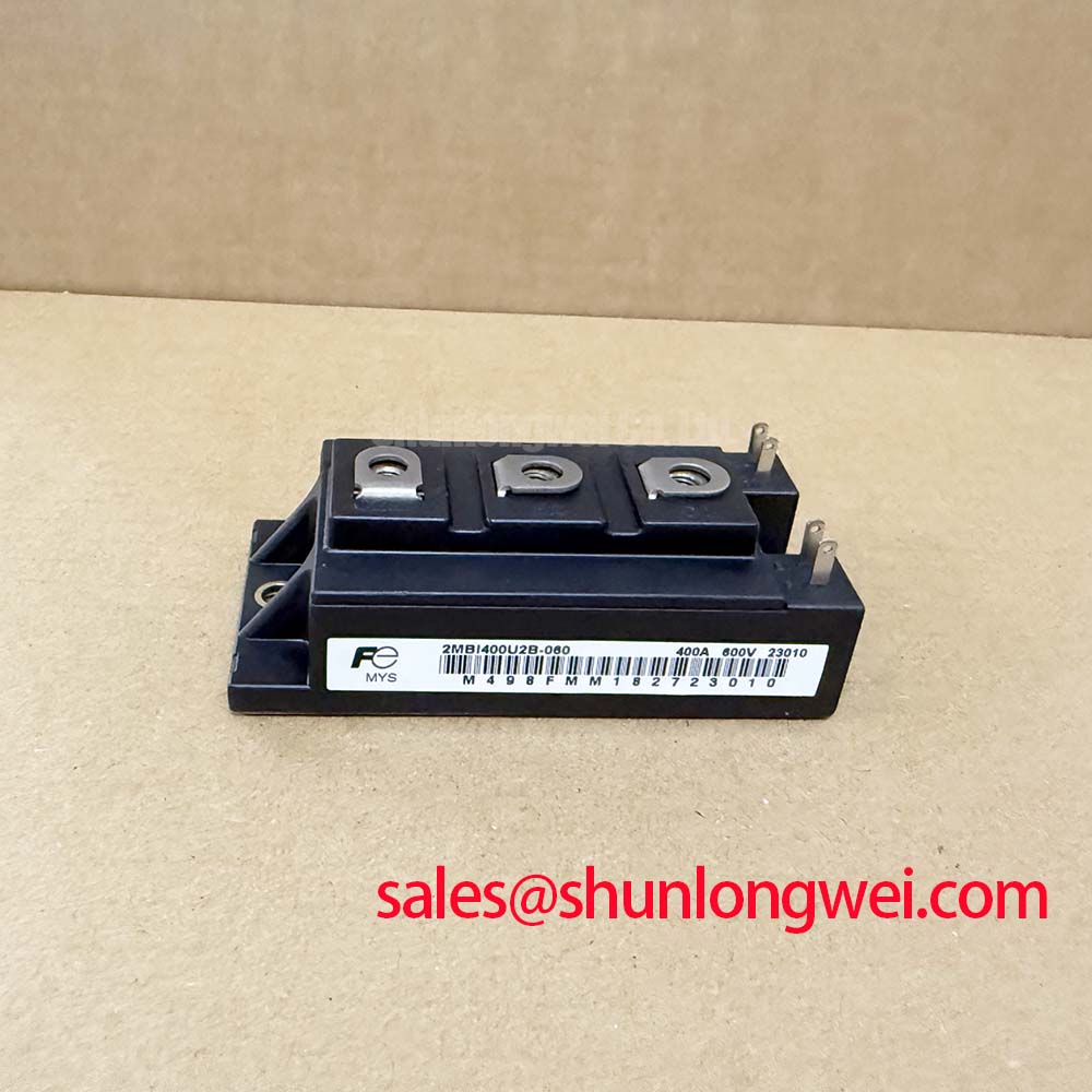
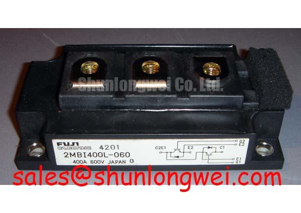
Operating high-current dual IGBT modules in demanding traction inverter architectures requires precise layout symmetry to control parasitic loop inductances. The Fuji Electric 2MBI400L-060 is a dual-pack (half-bridge) power module rated at VCES = 600V and a continuous collector current of IC = 400A at TC = 25°C (Official Datasheet Specification). In dual-switch topologies running dynamic switching cycles, asymmetric PCB trace geometry between the high-side and low-side gate-drive circuits introduces unbalanced stray inductances. These parasitic imbalances induce cross-talk, dynamic current unbalance, and localized overtemperature across the internal silicon dies.
A primary failure mode in high-power switching bridges stems from mutual inductance coupling between the main emitter power return path and the gate-emitter drive loop. When high di/dt currents pass through the main emitter, parasitic inductance in the power path develops a transient voltage drop that opposes the gate-drive command. To prevent spurious turn-on and high-frequency gate oscillations, the gate-drive circuit must connect exclusively to the dedicated auxiliary Kelvin emitter terminal provided on the 2MBI400L-060 package rather than tapping into the primary high-current DC-bus return.
Minimizing total loop area is essential when laying out the driver board directly above the power module terminals. The forward gate signal and the auxiliary emitter return trace must be routed as tightly coupled differential striplines or twisted pairs on adjacent PCB layers. Keeping the loop inductance below 15 nH (Design Consideration for low-inductance driver stages) mitigates high-frequency resonance with the module input capacitance Cies. In retrofits and auxiliary converter channels where lower current handling is specified, designers frequently evaluate compatible half-bridge configurations such as the 2MBI150-060 to balance dynamic footprint requirements.
💡 Pro Tip: To suppress parasitic Miller capacitance induced turn-on (dV/dt shoot-through), incorporate an active Miller clamp circuit directly at the gate driver stage. When the gate-to-emitter voltage drops below 2.0V during the turn-off transition, the active clamp clamps the gate directly to the negative supply rail through a low-impedance path, preventing spurious gate charge accumulation during rapid collector-emitter voltage transients.
| Parameter | Official Rating / Value | Engineering Significance |
|---|---|---|
| Collector-Emitter Voltage (VCES) | 600 V | Maximum blocking voltage capability (Official Datasheet Specification) |
| Continuous Collector Current (IC) | 400 A | Continuous current rating at case temperature TC = 25°C |
| Saturation Voltage (VCE(sat)) | 2.1 V (Typical) | Low conduction drop reducing thermal dissipation at 400A |
| Maximum Power Dissipation (Ptot) | 1500 W | Maximum allowable power loss per element (TC = 25°C) |
| Configuration | 2-Pack (Half-Bridge) | Integrated high-side and low-side phase leg |
Suppression of 2x V_DC Voltage Doubling at Inverter-Driven Motor Terminals
In high-speed rail auxiliary propulsion and heavy locomotive blower drives, long motor lead cables present an impedance mismatch between the inverter output terminals and the traction motor stator windings. The rapid switching speed of the 2MBI400L-060, which exhibits low typical saturation voltage VCE(sat) = 2.1V (Official Datasheet Specification), results in steep output voltage edges where dV/dt values can exceed 5 kV/μs. As these high-speed voltage wavefronts propagate along long unshielded or shielded traction cables, wave reflection occurs at the motor terminals due to the surge impedance mismatch between the cable and the motor windings.
Under full transmission line reflection, the standing wave phenomenon can cause the peak voltage at the motor terminals to reach nearly two times the internal DC-link bus voltage (2× VDC). For a 600V-class inverter operating on a nominal 350V to 400V DC-link, transient terminal spikes can surge past 750V to 800V, stressing the motor winding inter-turn dielectric insulation and accelerating partial discharge breakdown.
Mitigating this voltage doubling requires tailored passive filtering at the inverter output. Series dV/dt output chokes combined with damping resistors slow down the transition times, limiting dV/dt to below 1 kV/μs (Design Consideration for standard inverter-grade insulation). In high-power installations where full sinusoidal output is required, engineers integrate comprehensive LC low-pass sine-wave filters. For intermediate capacity locomotive sub-drives requiring precise power coordination, hardware designers frequently benchmark adjacent phase modules, such as the 2MBI300J-060, within complementary converter cabinets.
⚠️ Field Alert: When bolting busbars and output cable lugs to the power terminals of the module, always observe mechanical torque limits. Applying an uncontrolled torque to M5 or M6 terminal posts risks fracturing the internal substrate or compromising the package seal. A standard mounting torque of 2.5 to 3.5 N·m (General Industry Design Consideration for M5 screw fixings) must be maintained using a calibrated torque wrench during maintenance assembly.
Calculating Failures-in-Time (FIT) Rates in High-Altitude Solar and Wind Farms
When high-power converter equipment is deployed at elevated altitudes exceeding 2000 meters—such as mountain railway corridors, elevated wind turbines, and high-altitude solar installations—the terrestrial cosmic ray atmospheric neutron flux increases significantly compared to sea-level baselines. High-energy atmospheric neutrons colliding with the silicon crystal lattice of the power semiconductor can generate localized electron-hole plasma filaments within the high-voltage drift region, initiating a catastrophic phenomenon known as Single Event Burnout (SEB).
Because the 2MBI400L-060 has a maximum collector-emitter voltage limit of VCES = 600V (Official Datasheet Specification), derating guidelines must be applied to maintain an acceptable long-term FIT (Failures-in-Time, defined as failures per 109 component hours). In standard sea-level terrestrial industrial installations, running the module with an operating DC-bus voltage of 350V to 400V provides standard reliability. However, at high altitudes, the accelerated SEB failure rate demands a systematic reduction in continuous steady-state bus voltage.
To reduce switching and conduction stress in high-altitude renewable conversion systems, advanced topologies are frequently employed. Engineers utilize an interleaved boost converter topology to divide the input current, which lowers the DC-link input ripple current and minimizes baseline voltage fluctuation across the DC bus. Furthermore, transitioning from hard-switched converters to soft-switching resonant architectures—such as zero voltage switching (ZVS) resonant converter topologies—substantially reduces dynamic peak turn-off overvoltages, maintaining device operational boundaries well below critical breakdown levels.
Field engineering and reliability design standards (such as JEDEC JESD89A and IEC 62364) outline cosmic-ray-induced SEB susceptibility profiles. For critical traction and remote renewable installations, establishing continuous operational bus margins at approximately 55% to 65% of rated VCES (Design Consideration for high-altitude neutron derating) provides a stable starting point for long-term power stage qualification.
Mitigating Hard Switching Transients via Active Desaturation Soft Shutdown
Traction converters and high-capacity motor inverters operate under severe electrical environments where short circuits across the DC bus or output terminal load faults can occur. Under a fault event, short-circuit current rises rapidly, pushing the IGBT out of saturation into the active linear region where collector-emitter voltage rises abruptly while carrying fault currents several times higher than the rated IC = 400A. The total power dissipation during this phase can exceed the module's rated Ptot = 1500W by orders of magnitude.
To protect the 2MBI400L-060, the gate-driver circuit must feature high-speed desaturation (DESAT) detection capable of detecting the fault and initiating protective shutdown well within the 10 μs short-circuit withstand boundary (Official Datasheet Specification). Standard DESAT sensing utilizes a high-voltage fast-recovery diode coupled to the collector terminal to monitor the on-state VCE voltage. If VCE fails to drop below a predefined threshold (typically 6.5V to 8.0V) after a blanking filter interval (suggested 1.5 to 2.5 μs blanking time as a Typical Starting Point for bench tuning), the driver triggers a fault condition.
An abrupt gate turn-off during peak short-circuit currents causes an extreme rate of current decay (high di/dt). This rapid current drop interacts with the stray loop inductance (Lσ) of the DC busbar, inducing a dangerous transient overvoltage spike across the module terminals. If this transient voltage exceeds the 600V blocking limit, dynamic avalanche breakdown and immediate failure will occur.
Implementing an active two-stage soft turn-off (2-Stage Soft Shutdown) prevents this scenario. Upon DESAT fault detection, the driver reduces the gate-to-emitter voltage from +15V down to an intermediate clamping level (e.g., +8V) for a controlled duration (1 to 2 μs) before pulling the gate fully negative. This intermediate plateau reduces the di/dt slope during channel switch-off, clamping the peak inductive turn-off surge safely below the module rating.
For detailed laboratory validation, dynamic short-circuit waveform capture, and failure isolation workflows across inverter assemblies, consult the standardized methodologies documented in the Field Engineer’s Handbook.