Content last revised on October 14, 2026
Incoming Inspection: Identifying the 2MBI150NC-060
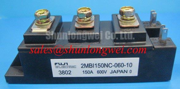
With the DC link discharged and the module disconnected from its driver, match each power and gate terminal to the circuit diagram before taking cold-state measurements. The 2MBI150NC-060 is a Fuji Electric IGBT module with a 600 V voltage rating and a 150 A current rating. These ratings establish the initial electrical identity for incoming inspection and replacement assessment; they are not a recommended operating point.
Record meter polarity, module temperature, and disconnected terminal conditions alongside each reading. Where the circuit diagram identifies a freewheeling diode path, compare its diode-mode response with a known-good module under the same conditions; a handheld meter reading is not a rated-current forward-voltage measurement. 💡 Bench Tip: Use ESD protection while handling gate terminals, and compare cold-state readings only after removing external circuit paths that could distort the result.
Transient Dynamics & Electrical Design: High-Frequency Common-Mode Bearing Current on 2MBI150NC-060
Compare switching waveforms at the inverter output and motor terminals when long motor leads accompany unexplained voltage excursions. As a Design Consideration, cable impedance discontinuities can produce reflected-wave overshoot at the motor, while parasitic coupling can carry common-mode current through the motor frame and bearing paths. These mechanisms require separate measurements: motor-terminal ringing does not establish the voltage stress across the module, and bearing current does not establish module damage.
Use appropriately rated differential probes and keep measurement connections compact. Capture collector-emitter voltage at the module terminals as well as the remote motor waveform, documenting DC-link voltage, load condition, cable arrangement, and switching settings. Changing the probe connection can alter apparent ringing, so repeat suspicious measurements with a controlled setup before changing the power stage.
Engineering Recommendation: evaluate output filtering against the measured cable response, motor insulation requirements, and inverter control behavior. A differential-mode filter addresses a different current path from a common-mode choke; selecting either solely from the module current rating overlooks the actual disturbance. Filter inductance, damping, heating, and placement should follow the system design and subsequent waveform validation.
At the module interface, separate sensitive gate wiring from switched power conductors and preserve the assembly’s specified electrical clearances. For technology context, Fuji Electric’s RC-IGBT module information discusses a distinct device family; it does not establish the internal construction or switching characteristics of the 2MBI150NC-060.
Benchtop Waveform Tuning: Mitigating Stress via Main Power Terminal Contact Resistance on 2MBI150NC-060
Measure each assembled power-terminal joint with a four-wire micro-ohmmeter, placing the voltage-sense contacts across the joint rather than across an arbitrary length of busbar. As a Design Consideration, repeatability matters more than imposing an unsupported universal resistance limit. Surface condition, fastener assembly, conductor geometry, and measurement temperature all affect the result; record them before comparing joints.
During a controlled load test, compare terminal temperatures using consistent thermographic viewing conditions. Reflective metal surfaces can make apparent temperatures misleading, so correlate the image with electrical measurements and the approved temperature-measurement method. A localized hot joint warrants inspection of seating and conductor contact, while broad heating calls for assessment of the entire current path and cooling arrangement. Neither pattern alone identifies a failed semiconductor.
Waveform tuning should distinguish contact heating from commutation stress. As a Design Consideration, freewheeling-diode reverse recovery can interact with loop inductance to create voltage overshoot and ringing. Observe the switching transition under defined load and temperature conditions before adjusting gate damping or evaluating a snubber. Snubber placement and dissipation must address the measured commutation loop, not merely improve the appearance of an oscilloscope trace.
For replacement assessment, compare the 7D150D-050EHR through its own circuit diagram, terminal arrangement, mounting drawing, and electrical characteristics. Its inclusion in a comparison does not establish interchangeability. Procurement records should retain the required module designation and revision information alongside the equipment bill of materials.
Field Diagnostics & Commissioning: Pollution Degree 3 Creepage Distances in 2MBI150NC-060 Topologies
Inspect terminal surfaces, insulating barriers, and the surrounding busbar assembly for conductive deposits before evaluating insulation performance. Pollution Degree 3 is an insulation-coordination condition, not an intrinsic rating established by the 2MBI150NC-060 model name. As a Design Consideration, assess creepage and clearance using the equipment’s working voltage, material classification, installation environment, and applicable IEC 60664-1 requirements.
Keep insulation-resistance measurement separate from dielectric-withstand testing. Their purposes, test connections, and acceptance criteria differ. Select the procedure from the manufacturer’s insulation instructions and the equipment service specification, including which terminals are interconnected and which auxiliary circuits must be isolated. An arbitrary high-voltage test can stress connected electronics without providing a meaningful module acceptance result.
Document the test voltage, duration, temperature, humidity, and instrument configuration. A change in measured resistance can justify cleaning, drying, or further examination, but it does not independently prove damage to an internal substrate. Limit incoming inspection to observable external conditions and approved electrical tests rather than inferring an undocumented ceramic construction.
Cooling-interface inspection belongs in the same commissioning record: check heatsink contact surfaces, interface-material condition, and mounting flatness against the assembly instructions. The article The Advanced Thermal Management Revolution provides broader thermal-management context, not evidence that this module uses any particular substrate or double-sided cooling architecture.
Assembly Integrity & Layout Architecture: Implementing Driver Power Stage Start-Up Inrush Mitigation for 2MBI150NC-060
Establish a defined gate-off state and functioning driver interlocks before enabling the DC-link power path. Engineering Recommendation: check auxiliary-supply startup, undervoltage-lockout behavior, and gate-emitter waveforms together. Negative gate bias, where specified by the approved driver design, must remain within the module’s gate limits; it is not a universal requirement or a substitute for checking actual startup behavior.
Separate DC-link precharge from driver initialization in the commissioning sequence. Precharge manages capacitor charging current, while driver sequencing prevents unintended switching during supply transitions. Verify inhibit behavior during startup, shutdown, and auxiliary-power interruption, including the interval when control logic is operating but the driver supply is not yet stable.
For complementary switching, assess dead time against measured turn-off behavior and driver propagation differences. Keep gate-drive return routing distinct from high-current paths wherever the documented terminal arrangement permits; do not assume a dedicated Kelvin-emitter terminal. Fuji Electric’s 7th-Gen X-Series IGBT information offers contemporary product-family context without assigning those features to this model.
When reviewing another power stage in the same equipment, treat the 2MBI50J-060 according to its own driver and protection requirements, not as an assumed front-end rectifier. Electric material-handling and forklift low-voltage traction assemblies are potential compatibility-assessment examples: designers should verify module losses, terminal fit, cooling, and control compatibility against the original equipment design. Finish commissioning by recording gate-off stability and interlock operation before authorizing loaded switching tests.