
Content last revised on September 10, 2026
High dv/dt Cross-Conduction Shoot-Through Mitigation via Dedicated Miller Clamps
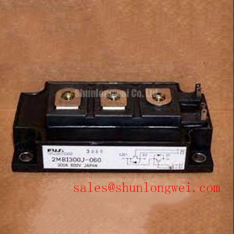
In high-altitude wind turbine pitch and yaw converter applications operating above 3000 meters, reduced air density impairs convective heat transfer and lowers dielectric breakdown thresholds. When driving the 2MBI300J-060 dual-pack IGBT module under fast switching conditions, steep collector-emitter voltage transients (high dv/dt) induce displacement currents through the internal collector-gate capacitance (Cres / Cgc). If this parasitic charging current flows through the external gate turn-off resistance unchecked, it generates a transient voltage rise across the gate-emitter terminals. Should this voltage exceed the gate-emitter threshold voltage of VGE(th) = 6.0V (Official Datasheet Specification), parasitic turn-on and catastrophic half-bridge shoot-through occur.
To eliminate cross-conduction risks without compromising switching speeds, drive boards should incorporate an active Miller clamp circuit or a regulated negative turn-off bias (such as -5V to -15V). Active Miller clamping routes displacement currents directly to the negative rail through an auxiliary low-impedance switch once the gate voltage falls below approximately 2.0V during turn-off. For auxiliary dynamic braking or chopper stages operating in adjacent sub-assemblies, designers frequently reference Fuji Electric Brake Chopper IGBT Modules to evaluate standardized clamp topologies and inductive snubber configurations.
💡 Bench Tip: During incoming inspection, verify gate-emitter integrity before unboxing ESD protection clips. Use a calibrated curve tracer to confirm that zero-gate-voltage collector leakage current (ICES) remains below 1.0 mA at VCES = 600V (Official Datasheet Specification) with VGE = 0V. An elevated leakage baseline often signals electrostatic stress or internal oxide layer degradation caused by improper bench handling.
Thermal Paste Degradation Prevention and Mechanical Clamping Torque Calibration
Pitch converters experience frequent thermal cycles due to cyclic aerodynamic loading on turbine blades. The 2MBI300J-060 relies on its isolated copper baseplate to transfer heat across a maximum junction-to-case thermal resistance of Rth(j-c) = 0.11°C/W for the IGBT elements and 0.24°C/W for the inverse fast-recovery diodes (Official Datasheet Specifications). Maintaining this thermal boundary requires precise control of the Thermal Interface Material (TIM). Applying excessive thermal paste increases thermal resistance, while uneven spreading creates micro-voids where localized hot spots develop.
Apply non-silicone thermal compound using a screen-printing stencil to achieve a uniform wet thickness between 50 µm and 100 µm (Typical Starting Point for bench assembly). Tighten the M5 module mounting screws in a two-stage cross pattern: first pre-tighten diagonally to 1.0 N·m, then apply the final clamping torque within 2.5 to 3.5 N·m (Design Consideration for M5 hardware). This sequential approach accommodates baseplate convex bowing, ensuring even distribution across the heatsink without cracking the internal ceramic DCB (Direct Copper Bonded) substrate. For auxiliary converter branches requiring lower current handling, engineers often evaluate the pin-compatible 2MBI150-060 half-bridge module to balance mechanical layouts across the chassis.
Desaturation (V_CE(sat)) Detection & Two-Stage Soft Turn-Off Short-Circuit Protection
Turbine pitch drives face unpredictable mechanical jam events that can induce direct phase-to-phase shorts or ground faults. Under short-circuit conditions, the collector current can rapidly exceed the continuous rating of IC = 300A (at TC = 80°C) and reach pulse limits up to ICP = 600A (Official Datasheet Specification). The gate driver must detect this fault via desaturation sensing (monitoring VCE(sat) exceeding its nominal 2.1V typical level at Tj = 25°C) and isolate the module within the Short-Circuit Safe Operating Area (SCSOA) limit of under 10 µs.
Abruptly shutting down several hundred amperes of fault current causes a high di/dt condition across the total parasitic loop inductance (Lσ). The resulting turn-off overvoltage spike—governed by the relationship where total peak collector voltage equals DC link voltage plus the inductive transient Lσ × (di/dt)—can easily breach the absolute maximum rating of VCES = 600V (Official Datasheet Specification). Gate drive boards should implement a Two-Stage Soft Turn-Off (2SSTO) mechanism that lowers the gate voltage gradually over 2 to 4 µs during a fault, reducing di/dt and suppressing inductive voltage spikes safely beneath the breakdown threshold. For systems requiring discrete single-switch topologies rather than half-bridge assemblies, the related 1MBI300L-060 offers a 600V 300A single-IGBT configuration for discrete bridge architectures.
Detailed test procedures for verifying desaturation trip thresholds under inductive loads are documented in the Field Engineer’s Handbook, which covers bench diagnostic methods for detecting bonding-wire fatigue and gate-oxide degradation.
Evaluating Thermal Capacitance vs Heat Sink Time Constant under Surge Bursts
Emergency blade feathering in high-wind conditions subjects the power converter to short, high-energy current bursts. Because the heatsink thermal time constant typically spans several minutes, the heatsink acts essentially as an isothermal heat reservoir during sub-second electrical surges. Consequently, the internal thermal capacitance of the silicon chip and copper baseplate dictates junction temperature rise during transient overloads.
When calculating transient thermal margin under burst conditions, dynamic junction temperature (Tj) must be verified against transient thermal impedance curves using multi-RC Foster or Cauer network models rather than steady-state Rth(j-c) values. The module provides an insulation voltage rating of Viso = 2500V AC for 1 minute (Official Datasheet Specification), providing galvanic isolation between the internal power elements and the grounded baseplate. For comprehensive thermal modeling and lifetime estimation across advanced silicon platforms, consult technical documentation on Fuji Electric 7th-Gen X-Series IGBT Modules.
⚠️ Field Alert: When conducting bench isolation tests, limit the applied AC potential to 2500V for no longer than 60 seconds. High-potential testers must ramp the test voltage smoothly; sudden step voltages generate capacitive displacement currents across the DCB isolation layer that can permanently degrade module dielectric strength.