
Content last revised on September 19, 2026
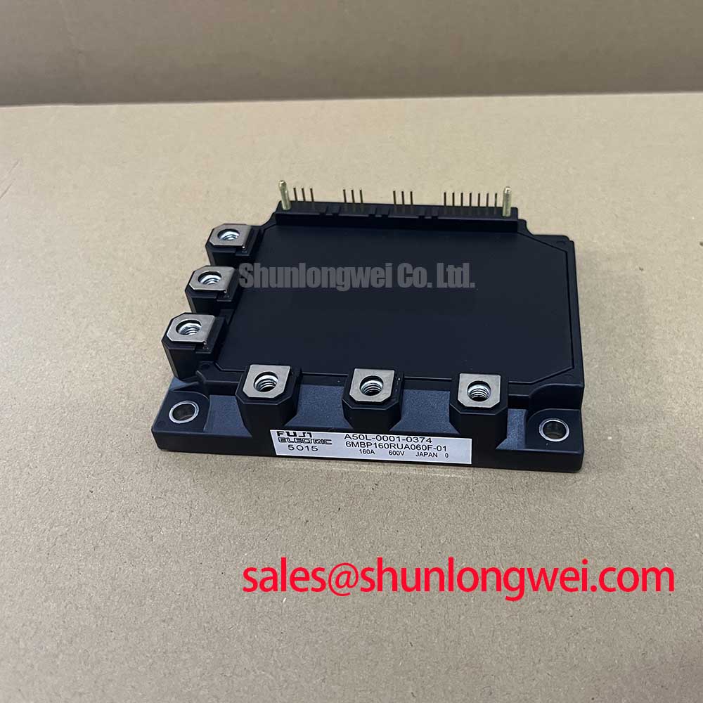
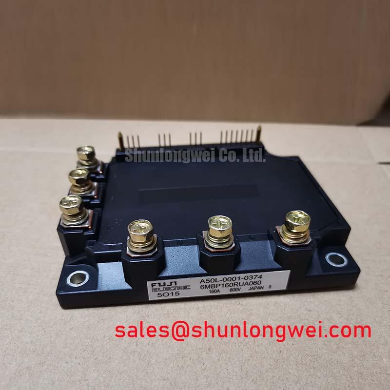
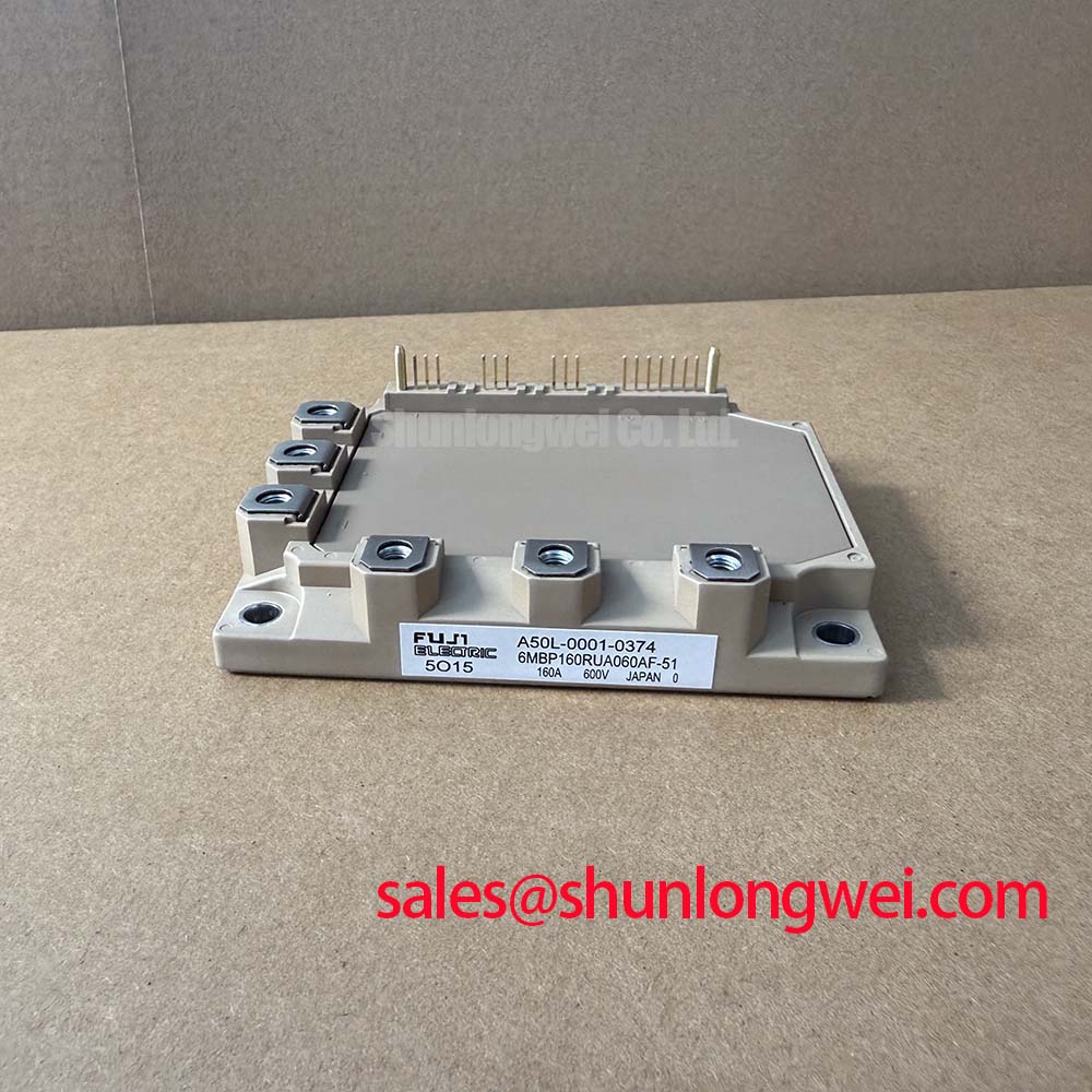
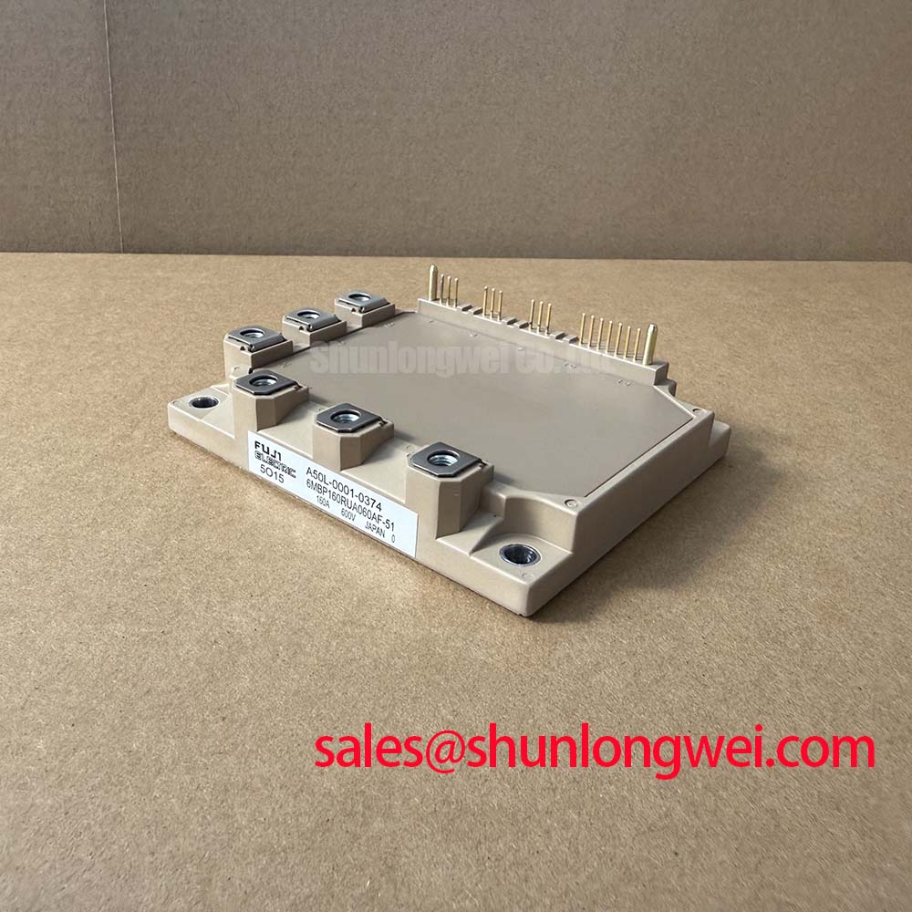
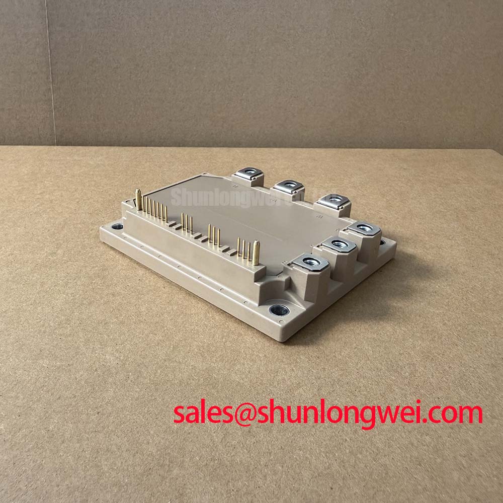
Field Diagnostics & Commissioning: Thermal Paste Degradation Prevention and Mounting in 6MBP160RUA060AF-51 Topologies
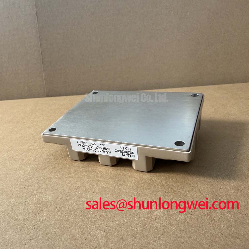
During field commissioning, isolate the DC link, wait for the equipment discharge procedure to complete, and inspect the mounting surface before removing the existing module. A dry, uneven, contaminated, or excessively thick thermal interface layer can create localized thermal resistance and produce temperature imbalance between the power module and heatsink. The interface material should cover the intended contact area evenly without visible voids, trapped particles, or large edge accumulations. The correct layer thickness is determined by the approved thermal interface material and the mechanical flatness of the heatsink, not by the module current rating alone.
Baseplate curvature and heatsink flatness should be assessed when a returned unit shows uneven contact transfer. A visible imprint concentrated along one edge can justify checking the mating surfaces, mounting sequence, screw alignment, and heatsink distortion. Use the equipment manufacturer’s specified fastener sequence and torque values. If no equipment-specific procedure is available, the required mounting method should be established from the module documentation and the mechanical design review rather than assumed from another package.
Sequential tightening helps distribute contact pressure progressively. The installer should keep the module seated naturally, avoid pulling it into position with one fastener, and confirm that the terminals are not carrying mechanical stress from busbars or cables. After assembly, verify that the power terminals, control connector, and isolation barriers are free from conductive debris. An electrical inspection should be performed before applying the DC link, followed by controlled waveform checks during commissioning.
For commercial string inverters and micro-grid energy storage converters, the relevant thermal investigation includes more than heatsink temperature. Compare phase-leg current, switching waveform shape, gate signal timing, and thermal behavior under the intended operating sequence. A difference between phases may result from gate-loop geometry, sensor placement, busbar asymmetry, cooling distribution, or control timing, so the technician should compare the complete signal path with a known-good assembly.
💡 Pro Tip: Never insert or remove the control connector while the converter is energized, because an uncontrolled gate state can create an unsafe switching event.
Assembly Integrity & Layout Architecture: Implementing Galvanic Gate Drive Isolation, Reinforced for 6MBP160RUA060AF-51
The module’s official isolation specification is 2500 V AC for 1 minute. This rating should not be reinterpreted as proof that a complete gate-drive system has reinforced isolation, a particular common-mode transient immunity, or compliance with a system-level safety standard. The isolation barrier, creepage path, clearance, transformer or isolator selection, PCB contamination control, and enclosure environment must be reviewed as one assembly. Designers should verify the required isolation category and test method against the applicable equipment standard.
Gate-drive isolation is most effective when the isolated control reference, power return, and switching-current path are clearly separated. Minimize the area of the gate-drive loop and keep high-current commutation conductors away from sensitive control traces. The final layout should be checked for parasitic coupling between collector or emitter power paths and gate-control conductors. During double-pulse or controlled-load testing, measure gate-to-emitter voltage at the module terminals rather than relying only on a remote driver test point.
Common-mode noise can appear as short gate disturbances when the switching node changes rapidly. A suitable isolated driver should be selected according to the actual switching environment, required transient immunity, propagation delay, supply behavior, and protection architecture. The requested design value for CMTI must be determined by the system engineer from measured switching conditions; the supplied product information does not establish a CMTI rating for this complete assembly.
Desaturation protection should monitor the semiconductor state during turn-on and initiate a controlled response when the expected saturation behavior is not achieved. The detection delay, blanking interval, fault latch, and soft turn-off profile are system design parameters. They must be validated against the module’s switching behavior, gate resistance, load current, DC-link voltage, and short-circuit test results. A two-stage response can be evaluated as a design consideration: first limit the gate command and then complete a controlled turn-off that avoids an excessive collector-emitter voltage excursion. The appropriate timing must be proven by oscilloscope testing rather than copied from an unrelated IPM.
Fuji Electric’s power semiconductor portal provides manufacturer-level product context. For incoming assembly inspection, an automated optical inspection reference can also help teams structure checks for terminal alignment, solder or contamination issues, and visible package defects, although optical inspection does not replace electrical testing.
6MBP160RUA060AF-51 Circuit Protection & Reliability: Calibrating Active Miller Clamp Implementation
High dv/dt at the switching node can couple through the gate-collector capacitance and disturb the complementary device’s gate-emitter voltage. An active Miller clamp is one possible design approach for reducing this effect, but its usefulness depends on the driver architecture, clamp impedance, gate-loop inductance, driver supply behavior, and the measured switching waveform. The clamp should be connected and validated with the shortest practical control-current path while preserving the isolation barrier and the manufacturer’s terminal arrangement.
Negative gate bias is not an established specification for this model in the supplied product data. Whether a negative turn-off level is appropriate depends on the selected driver, gate-emitter voltage limits, isolation supply design, turn-off transient, and the required protection response. Designers should not impose a fixed negative voltage without confirming the module’s official gate ratings and testing the complete driver circuit. A positive turn-off reference may be suitable in one system, while another may require a different protection strategy; the decision remains system determined.
When investigating possible cross-conduction, record both complementary gate-emitter waveforms at the module pins, the switching-node voltage, the DC-link current, and the driver fault signal. A disturbed gate waveform may originate from common-mode ground bounce, insufficient driver supply decoupling, an overly long control return, an incorrect dead-time relationship, or a damaged driver output. The measurement should therefore compare the entire half-bridge path rather than assign a single cause from one waveform.
Protection coordination is also important in bidirectional DC-DC battery converters. Repeated charge and discharge transitions can alter junction temperature, busbar temperature, and connector stress. The thermal design should be evaluated across the actual power-flow schedule, cooling airflow, switching frequency, and overload response. No field lifetime figure should be inferred from the module’s current rating. Temperature cycling, fault recovery, and long-duration validation require an application-specific test plan and documented evidence.
In systems that combine a front-end rectifier, DC link, and inverter bridge, the related 6MBI15L-060 may be reviewed as a neutral reference for a complementary topology position. Its suitability must be assessed independently from the 6MBP160RUA060AF-51 and verified against the original converter schematic.
Field Diagnostics & Commissioning: Derating Guidelines and Mismatched Parameters in 6MBP160RUA060AF-51 Topologies
The official 160 A continuous collector current rating is specified at Tc = 25°C. It should not be treated as a universal operating current for every heatsink, ambient temperature, switching frequency, overload profile, or enclosure. Derating is an Engineering Recommendation based on the complete thermal path and electrical duty. The system designer should determine the allowable current after reviewing case temperature, junction-temperature limits from the applicable documentation, switching losses, conduction losses, cooling performance, and transient operating conditions.
The typical 1.7 V VCE(sat) at rated current is useful for estimating conduction behavior, but it is not a substitute for measuring the installed phase leg. VCE(sat) changes with current, temperature, gate conditions, and measurement timing. Its positive temperature relationship can support static current-sharing behavior in parallel semiconductor paths, yet dynamic sharing still depends strongly on matched gate-loop impedance, symmetrical busbar geometry, driver timing, and emitter reference quality.
For a three-phase bridge, inspect phase symmetry at the module terminals and at the DC-link connection. A mismatch in switching overshoot or gate timing should prompt checks of conductor length, connector contact quality, isolated driver supply decoupling, sensor reference routing, and mechanical positioning. Verify peak voltage margins against the 600 V VCES rating during controlled switching tests, while accounting for the actual DC-link voltage and transient overshoot. The required margin is system determined and should be documented by measured evidence.
For replacement evaluation, compare the original equipment circuit, control connector assignment, cooling interface, protection logic, and mechanical envelope before procurement. The 6MBI100L-060 can be reviewed as a separate Fuji Electric module for comparison, but its electrical ratings, package details, and control compatibility must not be assumed to match this six-in-one 160 A inverter module.
When the converter uses resonant or soft-switching behavior, fault symptoms can change with operating frequency, load transition, and the selected commutation path. The engineering background in Resonant Topologies in Home Appliances may help frame topology-level checks, while the final diagnosis should remain tied to the actual inverter schematic, measured waveforms, and protection records.